
Stable clamping and traction device for erecting electric wire in power transmission line and use method of stable clamping and traction device

A technology of traction device and power transmission line, which is applied in transportation and packaging, overhead line/cable equipment, transportation of filamentous materials, etc. Easy-to-use effects

Pending Publication Date: 2022-03-15
CHINA THREE GORGES UNIV
View PDF0 Cites 1 Cited by
  • Summary
  • Abstract
  • Description
  • Claims
  • Application Information

AI Technical Summary

Problems solved by technology

However, due to the weight of the wires and cables themselves and the number of installations, during the installation and installation process, they encountered problems such as difficult handling and harsh installation environments, especially in places with steep terrain such as mountains and rivers. Huge difficulties, wasting a lot of manpower and material resources
[0003] In the prior art, the erection of transmission lines began to be operated by drones. The traction wires during the erection of power transmission lines were pulled up by drones, and at the same time, the traction wires were pulled by the movement of drones to pull the lost money. Although this method replaces the considered handling and erection, due to the weight of the traction line and the transmission line itself, and the traction line will be replaced by various models of different thicknesses according to the actual erection needs, when the drone is working, Often due to the heavy weight of the load, the problem of short working life is caused. At the same time, due to the different models of the traction wires, it is not easy to replace, which makes the erection and traction work efficiency lower.

Method used


Image

  • Stable clamping and traction device for erecting electric wire in power transmission line and use method of stable clamping and traction device
  • Stable clamping and traction device for erecting electric wire in power transmission line and use method of stable clamping and traction device
  • Stable clamping and traction device for erecting electric wire in power transmission line and use method of stable clamping and traction device

Examples


Embodiment

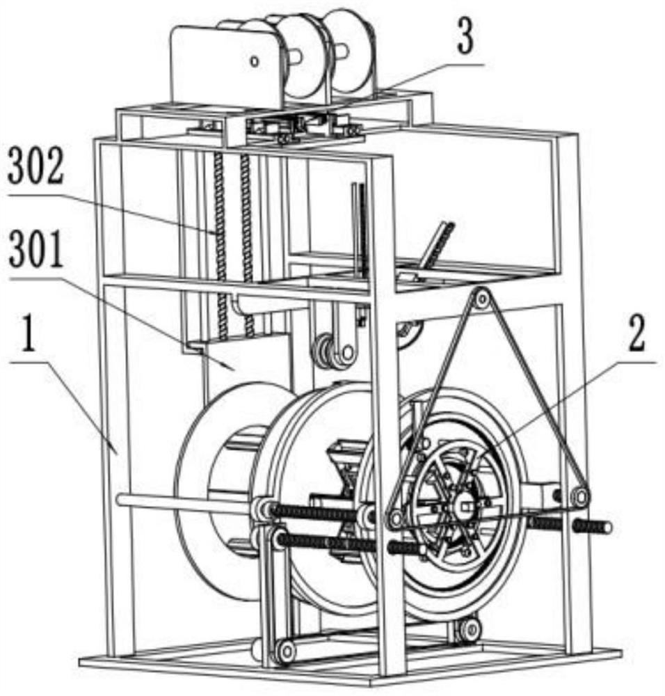
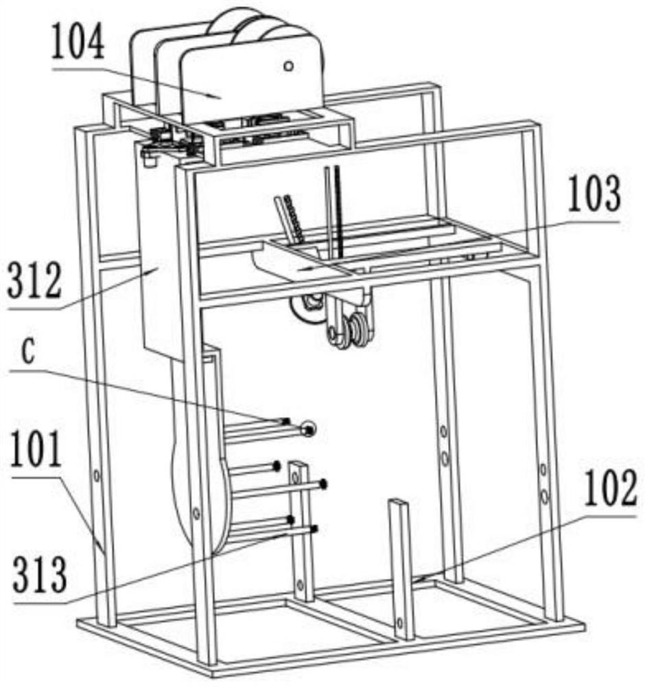
[0037] Example: such as figure 1 — Figure 13 The shown one is a stable clamping and pulling device for erecting electric wires in transmission lines, which includes an installation mechanism 1 , a winding mechanism 2 , and a lifting and locking mechanism 3 .

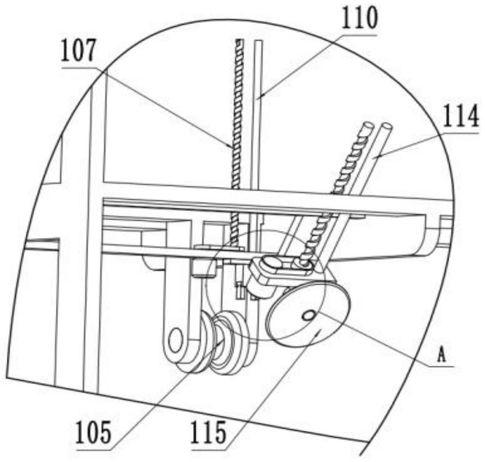
[0038] The installation mechanism 1 includes an installation frame 101 on which the winding mechanism 2 and the lifting and locking mechanism 3 are installed. The top of the mounting frame 101 is fixedly installed with a winding assembly 104, and the bottom end is fixedly mounted with two symmetrically arranged pulley mounting plates 102. The horizontal frame 103 is fixedly mounted on the mounting frame 101 and is located above the winding mechanism 2. On the horizontal frame 103 The winding wheel 105 is installed in rotation, the lifting motor one 108 is fixedly installed on the horizontal frame 103, the output shaft of the lifting motor one 108 forms a pulley with the input end of the lifting belt assembly one 109, a...


PUM


Abstract

The invention discloses a stable clamping traction device for erecting a wire in a power transmission line and a use method thereof, and belongs to the technical field of power equipment. The stable clamping traction device comprises a mounting mechanism, a winding mechanism and a lifting locking mechanism; the installation mechanism comprises an installation frame, and the winding mechanism and the lifting locking mechanism are installed on the installation frame. The winding mechanism comprises a rotating assembly and a winding roller, the winding roller is driven by the rotating assembly to clamp a pull wire, the erection of a power transmission line is facilitated, the lifting locking mechanism comprises a lifting assembly and a plurality of insertion rods, and the winding roller is wound and unwound through the lifting locking mechanism. Through the mounting mechanism, the winding mechanism and the lifting locking mechanism, the electric wire is automatically clamped in the erecting process, the structure is simple, and operation is convenient.

Description

technical field [0001] The invention belongs to the technical field of electric power equipment, and in particular relates to a stable clamping and pulling device for erecting electric wires in power transmission lines. Background technique [0002] With the development of urban modernization and rural construction, the erection of wires and cables has become the main task of social construction and development. Since the development of society cannot be separated from the use of power equipment, wires and cables are often hailed as the "nerve" and "Blood vessel". However, due to the weight of the wires and cables themselves and the number of installations, during the installation and installation process, they encountered problems such as difficult handling and harsh installation environments, especially in places with steep terrain such as mountains and rivers. Huge difficulties, wasting a lot of manpower and material resources. [0003] In the prior art, the erection of...

Claims


Application Information

Patent Timeline
Patent Type & Authority Applications(China)
IPC IPC(8): B65H49/32B65H67/02B65H51/06H02G1/02
CPCB65H49/32B65H67/02B65H51/06H02G1/02B65H2701/34Y02W30/82
Inventor 王启鉴
Owner CHINA THREE GORGES UNIV
Learn More