Load rejection structure for underwater equipment
A technology for underwater equipment and equipment, which is applied to underwater operation equipment, transportation and packaging, ships, etc., can solve the problems such as the inability to seal the cavity at the joint, the difficulty of bolt disconnection, and the large impact on the sealing performance of the equipment. Achieving the effect of ensuring sealing and uniform load-throwing force
- Summary
- Abstract
- Description
- Claims
- Application Information
AI Technical Summary
Problems solved by technology
Method used
Image
Examples
Embodiment 1
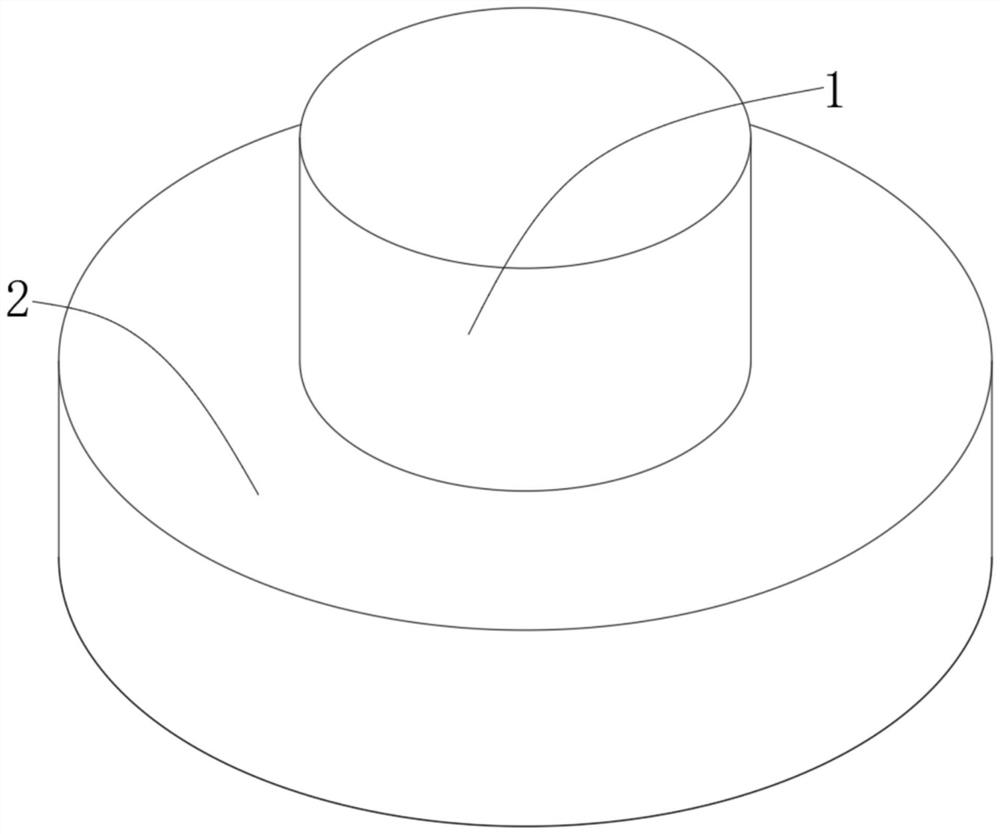
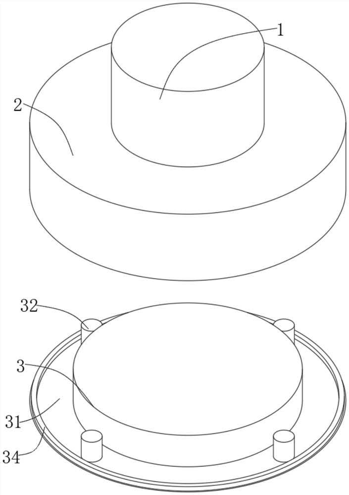
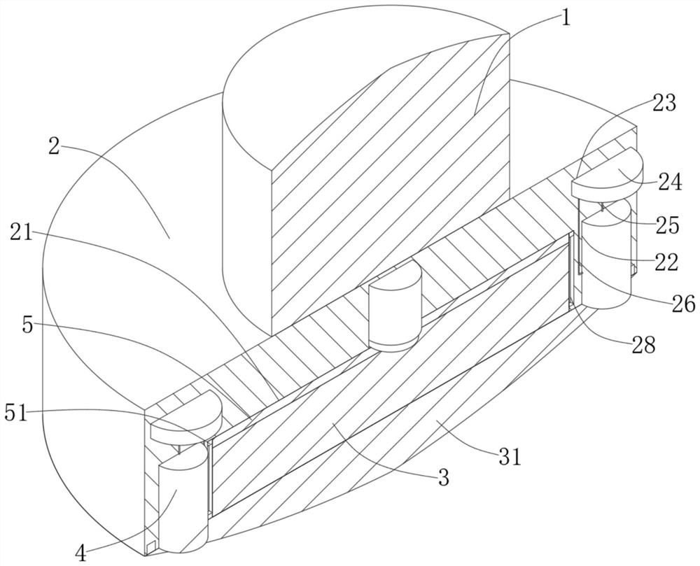
[0025] see Figure 1-5 , the present invention provides a technical solution: a load dump structure for underwater equipment, including a device body 1, the bottom surface of the equipment body 1 is fixedly connected to the load dump part 2, and a cylindrical sliding cavity 21 is set at the center of the bottom surface of the load dump part 2 , the cylindrical sliding cavity 21 is slidingly connected with the cylindrical heavy object 3, the bottom surface of the cylindrical heavy object 3 is fixedly connected to the heavy object arc-shaped bottom 31, and the top surface of the heavy object arc-shaped bottom 31 contacts the bottom surface of the ejection part 2, and the heavy object arc The top surface of the shaped bottom 31 is evenly fixed to four load dumping columns 32, and the bottom surface of the load dumping part 2 corresponds to the positions of the four dumping columns 32, and four installation column slots 22 are respectively opened;
[0026] The four mounting column...
Embodiment 2
[0028] see Figure 4 , the bottom surface and side wall of the sealed push plate 42 are affixed to the second electromagnet 49, the top surface of the ejection column 32 is fixedly embedded with the first electromagnet 33, and the inner wall of the bottom surface of the ejection sleeve 4 is affixed to the third electromagnet 410. The column 32 and the sealing push plate 42 are fixed to each other by the electromagnet. When dumping, the first electromagnet 33 on the top surface of the dumping column 32 is invalidated. After dumping the load dumping column 32, the sealing push plate 42 falls on the dumping On the bottom surface of the loading chamber 41, the third electromagnet 410 is started at this time, and the sealing push plate 42 is fixed on the bottom surface of the loading chamber 41 for sealing.
[0029] see Figure 4The top surface of the throwing cavity 41 is fixedly connected with a plurality of abutment columns 46, the bottom of the abutment column 46 contacts the ...
Embodiment 3
[0035] When the present invention is in a normal state, the first electromagnet 33 on the top surface of the dumping column 32 is in an open state, the third electromagnet 410 on the inner side wall of the bottom surface of the dumping chamber 41 is in a closed state, and the cylindrical weight block 3 is inserted into the column. In the sliding cavity 21, and the four dumping posts 32 are respectively plugged in the four dumping chambers 41, and the first electromagnet 33 on the top surface of the dumping post 32 and the second electromagnet 49 on the bottom surface of the sealing push plate 42 Absorb and fix, and when carrying out load dumping, power supply 24 is energized, and corroded wire 44 is corroded and fractured, and first spring 45 and second spring 47 apply force to sealing push plate 42 at this moment, can push down and carry out load dumping, in While dumping, the first electromagnet 33 on the top surface of the dumping column 32 is closed, and the third electroma...
PUM
 Abstract
Description
Claims
Application Information
 - R&D Engineer
- R&D Manager
- IP Professional
- Industry Leading Data Capabilities
- Powerful AI technology
- Patent DNA Extraction
Browse by: Latest US Patents, China's latest patents, Technical Efficacy Thesaurus, Application Domain, Technology Topic, Popular Technical Reports.
© 2024 PatSnap. All rights reserved.Legal|Privacy policy|Modern Slavery Act Transparency Statement|Sitemap|About US| Contact US: help@patsnap.com


