Real-time deformation monitoring method and system for frame section of tunnel shield tunneling machine under construction

A shield locomotive and deformation monitoring technology, applied in signal transmission systems, measuring devices, surveying and navigation, etc., can solve problems such as difficulty in erecting instruments, inability to continuously deform, and inability to monitor segments, and achieve high measurement accuracy and use. Safe and convenient effects

Pending Publication Date: 2022-03-11
SHANGHAI GEOTECHN INVESTIGATIONS & DESIGN INST
View PDF0 Cites 0 Cited by
  • Summary
  • Abstract
  • Description
  • Claims
  • Application Information

AI Technical Summary

Problems solved by technology

Among them, due to the influence of the frame and other construction equipment within the construction scope, the automatic monitoring of the total station makes it difficult to set up the instrument, and cannot monitor the deformation of the segment for a period of time after the installation; and the installation of the static level is difficult, As the shield construction process continues to advance, leveling points need to be added, and the entire monitoring system needs to be reinstalled and debugged, resulting in an inconsistency of deformation, and the static level can only monitor the settlement deformation of the tunnel segment, and cannot obtain the level of the tunnel segment displacement

Method used


Image

  • Real-time deformation monitoring method and system for frame section of tunnel shield tunneling machine under construction
  • Real-time deformation monitoring method and system for frame section of tunnel shield tunneling machine under construction
  • Real-time deformation monitoring method and system for frame section of tunnel shield tunneling machine under construction

Examples


Embodiment Construction

[0023] The present invention will be described in further detail below in conjunction with the accompanying drawings.

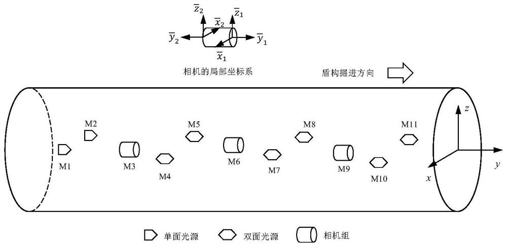
[0024] According to one or more embodiments, a real-time deformation monitoring system for the frame section of a shield machine under construction is disclosed, such as figure 1 As shown, it includes a light target and a test camera group. Along the traveling direction of the shield machine in the tunnel, the reference light target, the test camera group and the monitoring light target are arranged alternately in sequence. The light target and the test camera are fixed and installed. On the shield tunnel lining segments, they are arranged at intervals along the traveling direction of the shield machine. It also includes a wireless module installed on the test camera group and the light target for wireless communication, and a calculation system that receives data transmitted by the wireless module for calculation.

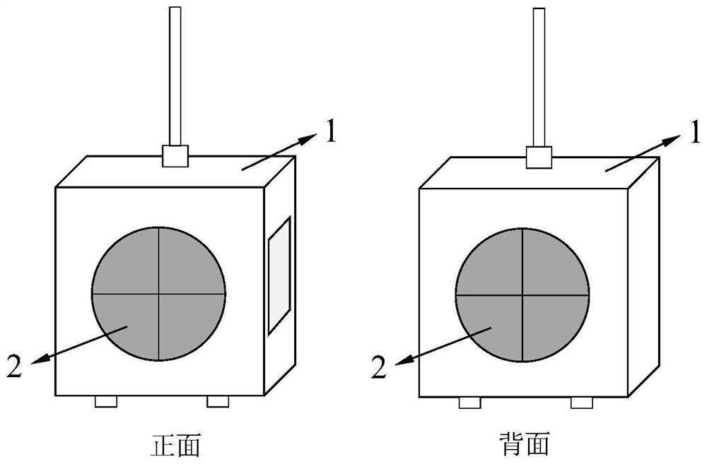
[0025] Such as figure 2 As shown, it is...


PUM


Abstract

The invention discloses a real-time deformation monitoring method and a real-time deformation monitoring system for a frame section of a shield tunneling machine in a tunnel under construction, and solves the defects that in the current shield tunneling process, duct piece deformation monitoring data are not obtained in time, conventional equipment is high in installation difficulty and poor in expansibility. Arranging a lamp target and a camera group, calibrating an initial position relation and establishing a local coordinate system; the wireless module remotely controls the camera and the lamp targets to synchronously start and work, images of all the target lamp targets are obtained, the pixel coordinates of the center point of the light-emitting face are obtained through the resolving system, the coordinate variable quantity of all the measuring points is resolved through a corresponding algorithm to obtain the accumulated deformation and the deformation of all the measuring points, the accumulated deformation and the deformation are compared with a preset threshold value, and the deformation of all the measuring points is obtained. According to the real-time deformation monitoring method and the real-time deformation monitoring system for the frame section of the tunnel shield tunneling machine under construction, the field installation is simple and convenient, the testing precision is high, and the system expansibility is good.

Description

technical field [0001] The invention relates to tunnel deformation monitoring technology, in particular to a real-time deformation monitoring method and system for a shield machine frame section of a tunnel under construction. Background technique [0002] With the rapid development of urban economy, cities are carrying out urban rail transit construction, and the shield method is mainly used for construction. The excavation process of the shield machine will cause disturbance of the surrounding groundwater and soil, resulting in uneven stress on the tunnel structure and differential deformation, especially the newly installed lining ring near the shield machine is prone to uneven settlement and horizontal lateral movement, and The amount of deformation is relatively large, and it will cause construction accidents in severe cases. Therefore, it is particularly important to monitor the deformation of the tunnel structure under construction in the frame section of the shield m...

Claims


Application Information

Patent Timeline
IPC IPC(8): G01C5/00G01B11/02G01B11/16G08C17/02
CPCG01C5/00G01B11/022G01B11/16G08C17/02
Inventor 褚伟洪陈卫南屠伟新苏辉张金凤陆石基李岳峰
Owner SHANGHAI GEOTECHN INVESTIGATIONS & DESIGN INST
Why Eureka
Try Eureka