
Current protection circuit and totem pole PFC circuit

A current protection and totem pole technology, applied in the field of circuits, can solve the problems of sudden change in control mode, abnormal circuit conditions, abnormal system operation, etc., to achieve the effect of reporting protection status and avoiding jumps

Pending Publication Date: 2022-03-08
SHENZHEN HUNTKEY ELECTRIC
View PDF0 Cites 0 Cited by
  • Summary
  • Abstract
  • Description
  • Claims
  • Application Information

AI Technical Summary

Problems solved by technology

In order to solve this problem, at present, people adopt the method of hardware protection circuit, that is, the current sampling signal passes through the amplifying circuit and then the comparator to judge whether the current is greater than the threshold value, and if so, turn off the drive, so that the response cycle can be very fast, but , it can only turn off the instantaneous current, and only one of the two switch tubes is turned off. The circuit is in abnormal condition, and the control chip cannot know this situation. The chip end still sends out the drive, and there is a risk of sudden change in the control mode, which may easily lead to abnormal operation of the system.

Method used


Image

  • Current protection circuit and totem pole PFC circuit
  • Current protection circuit and totem pole PFC circuit
  • Current protection circuit and totem pole PFC circuit

Examples


Embodiment Construction

[0019] The technical solutions in the embodiments of the present invention will be clearly and completely described below in conjunction with the drawings in the embodiments of the present invention, and similar component numbers in the drawings represent similar components. Apparently, the embodiments described below are only a part of the embodiments of the present invention, rather than all the embodiments. Based on the embodiments of the present invention, all other embodiments obtained by persons of ordinary skill in the art without creative efforts fall within the protection scope of the present invention.

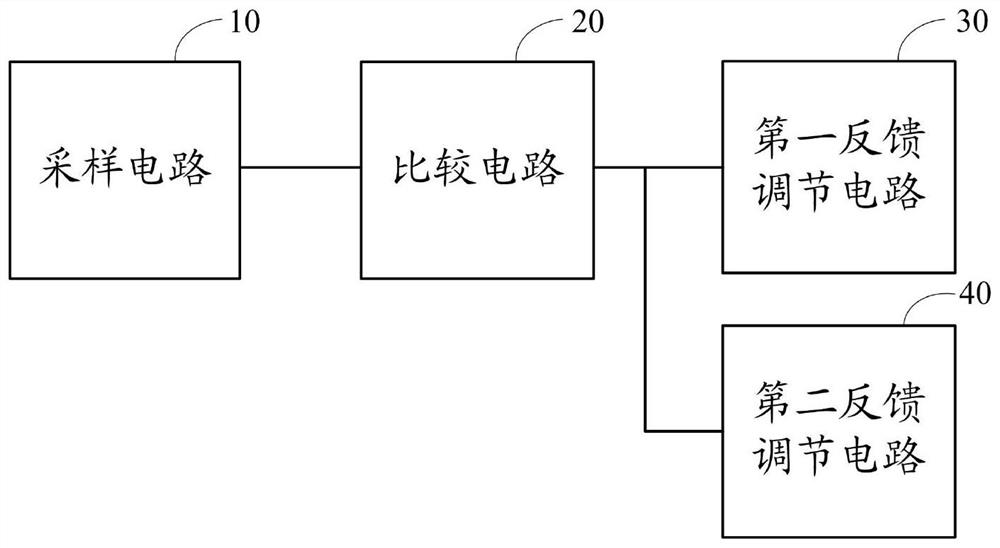
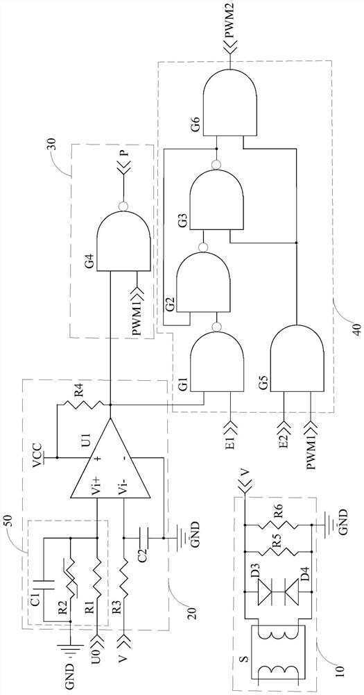
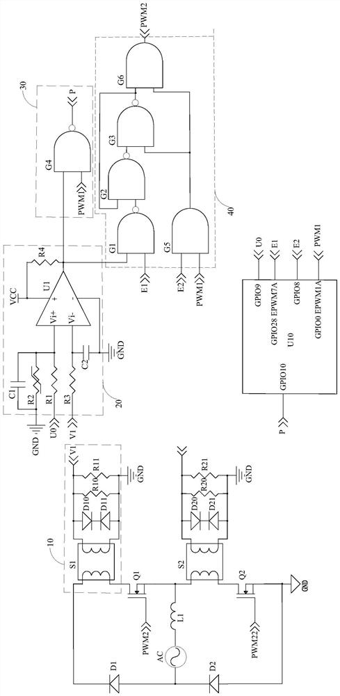
[0020] refer to figure 1 , the current protection circuit of the present invention is used for overcurrent protection of a totem pole PFC circuit, including a sampling circuit 10, a comparison circuit 20, a first feedback regulation circuit 30, and a second feedback regulation circuit 40, wherein the sampling circuit 10 is connected to the totem pole The switching t...


PUM


Abstract

The invention discloses a current protection circuit, which is applied to a totem-pole PFC circuit, and comprises a sampling circuit connected to a switching tube of the totem-pole PFC circuit so as to collect the working current of the switching tube; the comparison circuit is connected with the sampling circuit and is used for comparing the working voltage corresponding to the working current with the threshold voltage; the first feedback regulation circuit is connected between the comparison circuit and a control chip of the totem pole PFC circuit so as to output a protection report signal to the control chip when the working voltage is greater than the threshold voltage, so that the control chip is triggered to be interrupted; and the second feedback regulation circuit is connected with the comparison circuit to pull down a driving signal of a switching tube of the totem pole PFC circuit when the working voltage is greater than the threshold voltage so as to close the switching tube. The current protection circuit provided by the invention not only can realize rapid turn-off of a driving signal during overcurrent, but also can realize a function of reporting a protection state. The invention also discloses a totem pole PFC circuit.

Description

technical field [0001] The invention relates to the technical field of circuits, and more specifically relates to a current protection circuit and a totem pole PFC circuit. Background technique [0002] The totem pole power factor correction circuit is a topology capable of achieving high efficiency and low electromagnetic interference, which is composed of two switching tubes connected in series and two rectifier diodes connected in series. In recent years, in order to meet the requirements of high power density of the power supply, the switching frequency of the totem pole PFC tends to be high frequency, which makes the switching period of the power device smaller and smaller, and the current change rate is larger and larger, that is, the current rise time is shorter and shorter. . The current protection circuit traditionally applied to the totem pole bridgeless power factor correction circuit uses digital sampling to control the protection current, because the current sa...

Claims


Application Information

Patent Timeline
Patent Type & Authority Applications(China)
IPC IPC(8): H02H7/125H02H3/087H02M1/42H02M1/00H02M1/08
CPCH02H7/1252H02H3/087H02M1/4233H02M1/00H02M1/08Y02B70/10
Inventor 孟祥翰
Owner SHENZHEN HUNTKEY ELECTRIC
Learn More