
Method for testing gas production rate of battery

A test method and technology for gas production, which are applied in volume measurement instruments/methods, capacity measurement calibration, measurement devices, etc., can solve problems such as troublesome calibration operations, expensive vacuuming equipment, damage to battery casings, etc., and achieve practicality and safety. High performance, small gas dispersion space, and the effect of eliminating pressure interference

Pending Publication Date: 2022-03-08
HUBEI JINQUAN NEW MATERIALS CO LTD
View PDF2 Cites 0 Cited by
  • Summary
  • Abstract
  • Description
  • Claims
  • Application Information

AI Technical Summary

Problems solved by technology

When the volume of the battery changes, a certain pressure needs to be generated inside the battery, and water will generate a certain pressure on the submerged part of the battery. In summary, the gas production measured by this method is less than the actual gas production of the battery, and this method is not suitable for hard shell batteries.
[0004] 2. The gas collection method is mainly to collect the gas generated by the battery after the battery gas production is completed, and then test the gas content through the drainage method. On the one hand, this method cannot monitor the battery gas production in real time and continuously. On the other hand, there is a drainage method test Disadvantages of inaccurate results
This test method mainly has the following defects: (1) The test device must be equipped with acupuncture components, upper cavity component gaskets, air extraction PP pipes, valves, rubber plugs and other components, and the structure is complex; (2) The sealing oil column PP In the calibration process of the pipe, vacuum pumping is required, and PP pipes, valves, rubber plugs and supporting vacuum pumping equipment are also needed. Not only the calibration operation is troublesome, but also the vacuum pumping equipment is expensive and occupies a large area; (3) The test device is used to seal the finished battery, but the steel nail moves down to pierce the battery case, which will not only damage the battery case, but may also damage the inside of the battery, and may also cause the battery to explode, making it difficult to guarantee practicability and safety; ( 4) The test method is used to test the gas production in the finished battery, and it is impossible to monitor the gas production in real time and continuously during the formation process of the battery; (5) The test method is to introduce the gas from the inside of the battery in a small space into the device cavity in a large space As the gas dispersion space increases and the pressure decreases, in addition to overcoming the air resistance in the PP tube of the sealed oil column, the air resistance in the device cavity must also be overcome, so the force applied to the oil column decreases, so the test results The gas volume is less than the actual gas production of the battery; in addition, the test gas production will also be affected by the sealing of the device cavity itself, the sealing between it and the acupuncture component, the sealing between it and the suction PP tube, and the sealing of the sealing oil column PP Due to the influence of factors such as tube sealing, the accuracy of the test results of this test method is difficult to guarantee, and there are large errors
However, this test method mainly has the following defects: (1) The test device must have components such as a barometer, a first thermometer, a second thermometer, and a temperature adjustment mechanism, and the structure is complex; (2) This test method also needs to record The temperature and pressure values ​​of the gas in the container cavity and the temperature and pressure values ​​of the gas in the container cavity after the battery is formed, and the temperature difference and pressure difference are reduced by the second thermometer and the temperature adjustment mechanism, which is troublesome to operate; and it needs to pass through the target position The distance from the original position and the cross-sectional area of ​​the inner cavity are used to calculate the gas production of the battery, and the measurement method is complicated; (3) This test method can only be used to test the gas production after the battery is formed, and cannot be used for the gas production during the battery formation process. Real-time and continuous monitoring; (4) The gas inside the battery must enter the inner cavity of the container through the catheter, and the pressure of the catheter and the inner cavity of the container is increased to indirectly drive the movement of the piston, that is, the gas is introduced from the inside of the battery in a small space In a container with a large space, because the gas dispersion space increases, the pressure decreases, and the air resistance between the conduit and the container cavity must be overcome, the force applied to the piston part decreases, so the test gas production is less than the actual gas production of the battery; In addition, the test gas production will also be affected by the seal between the battery and the container itself, the seal between it and the conduit, the seal between it and the piston, the seal between it and the barometer, and the seal between it and the thermometer. Therefore, the accuracy of the test results of this test method is difficult to guarantee, and there are large errors
(5) The volume and weight of the piston part are much larger than the volume and weight of the oil column. If the gas production of the battery is not large enough, the force applied to the piston part is not enough to push the piston part to move. The test sensitivity is low and can only be used for Test the formation of a battery with a large gas production

Method used

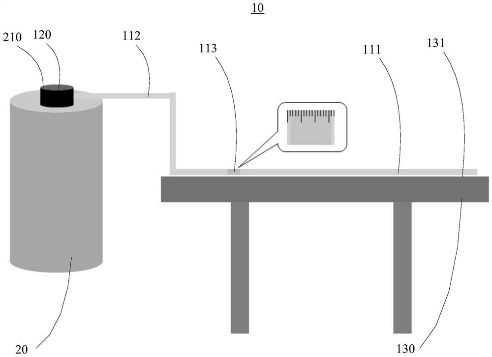
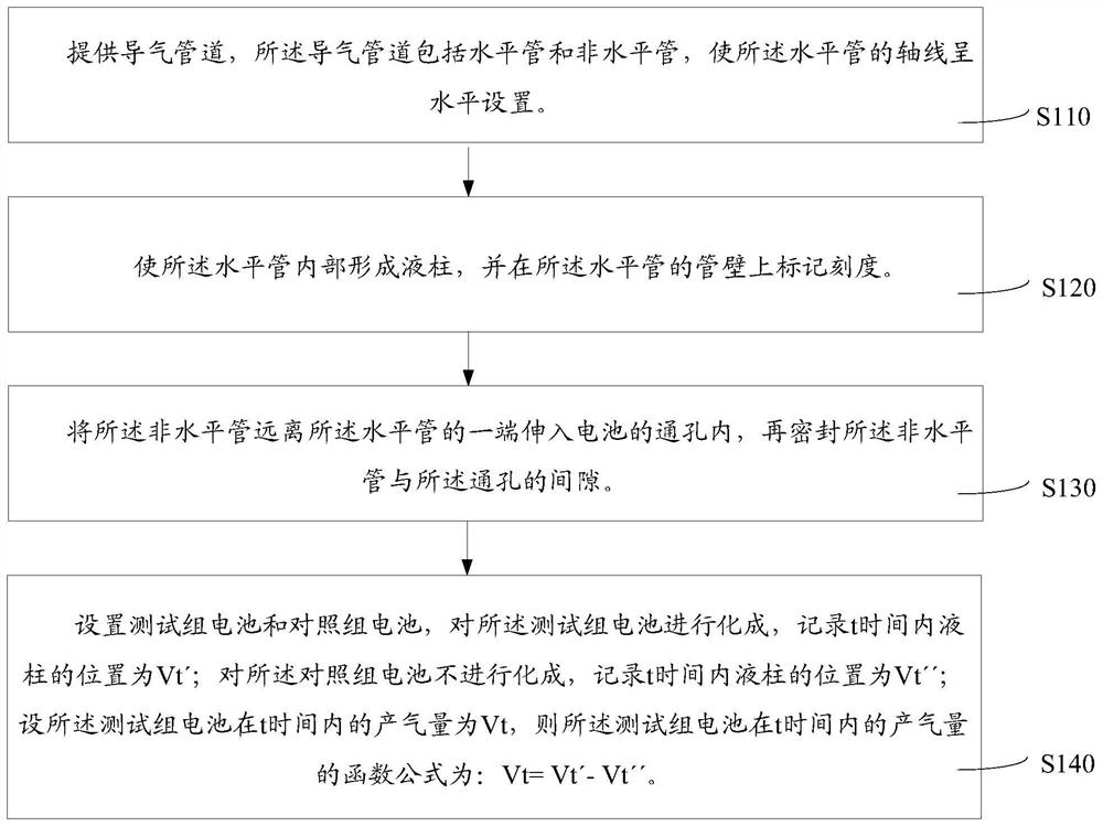
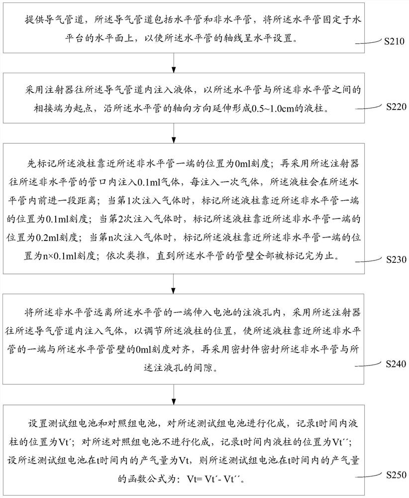

Image

  • Method for testing gas production rate of battery
  • Method for testing gas production rate of battery
  • Method for testing gas production rate of battery

Examples


Embodiment Construction

[0038] In order to facilitate the understanding of the present invention, the present invention will be described more fully below with reference to the associated drawings. Preferred embodiments of the invention are shown in the accompanying drawings. However, the present invention can be embodied in many different forms and is not limited to the embodiments described herein. On the contrary, the purpose of providing these embodiments is to make the disclosure of the present invention more thorough and comprehensive.

[0039] For an example, see figure 2 , a method for testing battery gas production, comprising the following steps:

[0040] S110, providing an air guide pipe, the air guide pipe includes a horizontal pipe and a non-horizontal pipe, and the axis of the horizontal pipe is arranged horizontally, so as to avoid the influence of gravity on the liquid column inside the horizontal pipe.

[0041] S120, forming a liquid column inside the horizontal tube, and marking...


PUM


Abstract

The invention relates to the field of batteries, and discloses a method for testing the gas production rate of a battery, which comprises the following steps: providing a gas guide pipeline which comprises a horizontal pipe and a non-horizontal pipe, and enabling the axis of the horizontal pipe to be horizontally arranged; a liquid column is formed in the horizontal pipe, and scales are marked on the pipe wall of the horizontal pipe; extending one end, far away from the horizontal pipe, of the non-horizontal pipe into the through hole of the battery, and sealing a gap between the non-horizontal pipe and the through hole; setting a test group battery and a control group battery, and recording the position of a liquid column within t time of the formed test group as Vt '; recording the position of the liquid column of the control group which is not subjected to formation within the time t as Vt ''; the function formula of the gas production rate of the tested battery pack within the time t is Vt = Vt '-Vt'. The testing method is simple to operate, high in testing sensitivity and high in testing accuracy, and the gas production rate in the battery formation process can be continuously monitored in real time.

Description

technical field [0001] The invention relates to the field of batteries, in particular to a method for testing battery gas production. Background technique [0002] During the battery production process, there will be a formation stage, and the electrolyte and the negative electrode material will react to form an SEI film, which will generate a large amount of gas. The amount of gas produced can reflect whether the film-forming reaction of the SEI film is complete from the side, and the amount of gas produced is also an indicator for evaluating the safety performance of the battery. an important indicator. At present, the test methods for the gas production of the battery are mainly the drainage method and the gas collection method. The two methods have the following disadvantages respectively: [0003] 1. The drainage method mainly uses the volume change before and after battery gas production, which indirectly reflects the difference in drainage volume when the battery is ...

Claims


Application Information

Patent Timeline
Patent Type & Authority Applications(China)
IPC IPC(8): G01F19/00
CPCG01F19/00
Inventor 王震杨佰龙罗有缘刘静徐悦斌何巍
Owner HUBEI JINQUAN NEW MATERIALS CO LTD
Learn More