


Quick Research
Generate reliable direction feasibility study reports for your R&D in just a few steps.

Technical Q&A
Discover and master advanced knowledge NOW. Basics, ideas, possibilities, all at once.

Find Solutions
As an expert in R&D theories, this can generate solutions to your technical problems instantly.

Evaluate Feasibility
Analyze your overall solution with one click, know your potential R&D risks in advance.

Monitor Landscape
Get weekly tech updates, stay abreast of the latest tech innovations and key insights.
Valve
A valve and valve cavity technology, applied in the field of valves, can solve problems such as the angle deflection of sealing fittings and affect the sealing effect, and achieve the effects of improving stress concentration, improving sealing effect, reliability and service life
- Summary
- Abstract
- Description
- Claims
- Application Information
AI Technical Summary
Problems solved by technology
Method used
Image

Examples
Embodiment 1
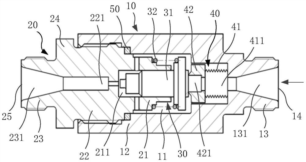
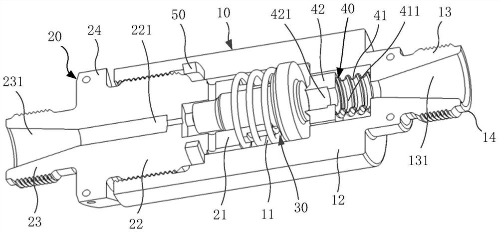
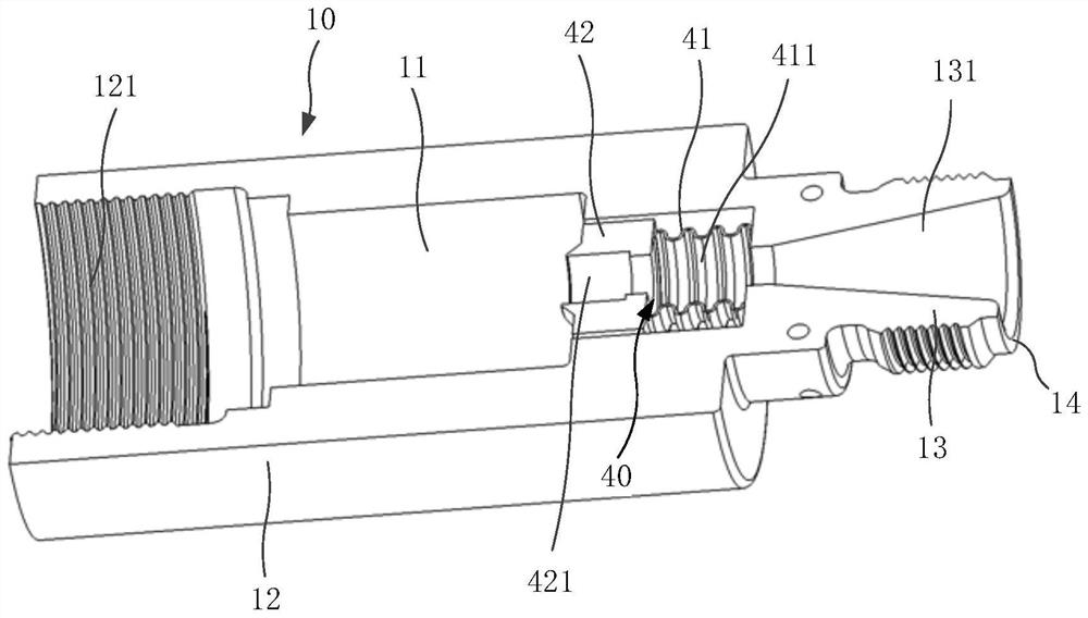
[0080] refer to Figure 7 with Figure 8 As shown, the fine-tuning assembly 40 includes a bellows 41 and a fixed seat 42. The two ends of the bellows 41 are respectively connected to the inner wall of the valve chamber 11 and the fixed seat 42. The fixed seat 42 is provided with an inner flow channel 421, the inlet 14 and the valve chamber. 11 communicates with the inner channel 421 through the inner pipe 411 of the bellows 41.
[0081] The fixing seat 42 can enhance the overall rigidity of the fine-tuning assembly 40. The bellows 41 can be fixedly connected to the inner wall of the valve cavity 11 by welding, and the bellows 41 can also be welded to an end surface of the fixing seat 42. way to achieve a fixed connection.
[0082] In a possible implementation manner, the outer diameter of the fixing seat 42 is larger than the outer diameter of the bellows 41 , and the inner diameter of the inner flow channel 421 is smaller than the smallest cross-sectional diameter of the in...
Embodiment 2
[0123] The difference between the second embodiment and the first embodiment is that the trimming assembly 40 includes a bellows 41, one end of the bellows 41 is fixedly connected to the inner wall of the valve cavity 11, the other end of the bellows 41 is in movable contact with the valve core assembly 30, and the inlet 14 communicates with the valve cavity 11 through the inner pipe 411 of the bellows 41.
[0124] In order to facilitate the formation of a sealing interface at the contact position between the trimming assembly 40 and the valve core assembly 30 , the end of the bellows 41 that is in movable contact with the valve core assembly 30 has a raised end 422 , and the raised end 422 faces away from the stem head 312 One side of the rod body 311 abuts against each other.
[0125]In this embodiment, the fixed seat 42 is omitted, and the inner pipe 411 of the bellows 41 communicates with the first flow channel 131 and the valve chamber 11, and the bellows 41 is directly a...
PUM
 Abstract
Description
Claims
Application Information
 - R&D Engineer
- R&D Manager
- IP Professional
- Industry Leading Data Capabilities
- Powerful AI technology
- Patent DNA Extraction
Browse by: Latest US Patents, China's latest patents, Technical Efficacy Thesaurus, Application Domain, Technology Topic, Popular Technical Reports.
© 2024 PatSnap. All rights reserved.Legal|Privacy policy|Modern Slavery Act Transparency Statement|Sitemap|About US| Contact US: help@patsnap.com