


Quick Research
Generate reliable direction feasibility study reports for your R&D in just a few steps.

Technical Q&A
Discover and master advanced knowledge NOW. Basics, ideas, possibilities, all at once.

Find Solutions
As an expert in R&D theories, this can generate solutions to your technical problems instantly.

Evaluate Feasibility
Analyze your overall solution with one click, know your potential R&D risks in advance.

Monitor Landscape
Get weekly tech updates, stay abreast of the latest tech innovations and key insights.
Patient transfer device for epidemic site
A transfer device and epidemic technology, applied in the field of medical devices, can solve the problems of inability to directly connect ambulances, manual handling, and troublesome processes, and achieve the effects of saving manpower, improving comfort, and improving transfer efficiency.
- Summary
- Abstract
- Description
- Claims
- Application Information
AI Technical Summary
Problems solved by technology
Method used
Image


Examples
Embodiment 1
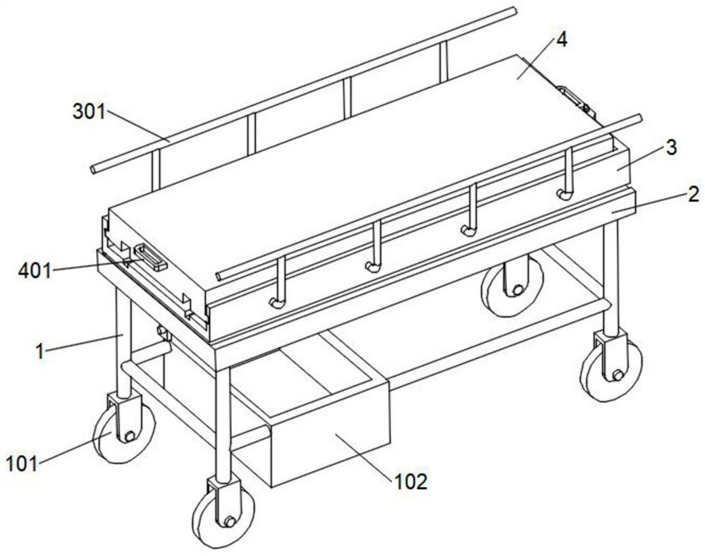
[0034] refer to Figure 1-6 An epidemiological site patient transfer device shown includes a main body support 1, a bottom plate 2 and a lifting plate 3, universal wheels 101 are fixedly installed at the four lower ends of the main body support 1, and a placing basket is fixed on the left side of the main body support 1 102, the upper end of the main body support 1 is fixedly installed with a bottom plate 2, and the inner sides of the bottom plate 2 are symmetrically provided with lifting components, the bottom of the bottom plate 2 is provided with a driving component, and the top of the bottom plate 2 is provided with a lifting plate 3, and the surfaces of both sides of the lifting plate 3 are symmetrically fixed and installed There are two groups of guardrails 301, a movable bed board 4 is slidably installed on one side of the lifting plate 3, and handles 401 are fixedly installed at both ends of the movable bed board 4.
[0035] Based on the above structure, when the devic...
Embodiment 2
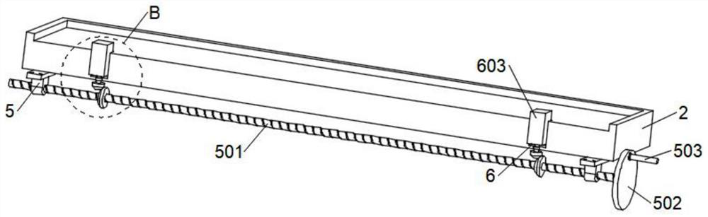
[0037] combine image 3As shown, based on the above-mentioned embodiment 1, the driving assembly includes two sets of fixing bases 5 symmetrically and fixedly installed on the lower surface of the bottom plate 2, and a screw A501 is rotatably installed between the two sets of fixing bases 5, and the two ends of the screw A501 respectively penetrate to the two sets of On the outside of the fixed seat 5, a turntable 502 is fixedly installed on the end of the left screw A501 coaxially, and a crank handle 503 is fixedly installed on the eccentric side surface of the turntable 502. By holding the crank handle 503 and shaking it, the turntable 502 will drive the screw A501. Rotate, through the meshing transmission effect of the bevel gear set 604, the screw rod A501 will drive the two sets of screw rods B602 to rotate synchronously.
Embodiment 3
[0039] combine image 3 and Figure 4 As shown, based on the above-mentioned embodiment 1 or 2, the lifting assembly includes limiting grooves 6 symmetrically opened on both sides of the upper surface of the bottom plate 2, the bottom of the limiting groove 6 is provided with a bearing 601, and the bottom of the limiting groove 6 is rotatably installed with a bearing 601. Screw B602, and the screw B602 penetrates to the bottom of the bottom plate 2, the inside of the limit groove 6 is slidingly installed with a lifting block 603, and the lifting block 603 is engaged and sleeved outside the screw B602, and the lower end of the screw B602 and the outer surface of the screw A501 are evenly spaced. A bevel gear set 604 is provided, and the screw rod B602 is connected to the screw rod A501 through the bevel gear set 604, and the end of the lifting block 603 is fixedly connected with the lower surface of the lifting plate 3. Through the meshing transmission of the bevel gear set 604...
PUM
 Abstract
Description
Claims
Application Information
 - R&D Engineer
- R&D Manager
- IP Professional
- Industry Leading Data Capabilities
- Powerful AI technology
- Patent DNA Extraction
Browse by: Latest US Patents, China's latest patents, Technical Efficacy Thesaurus, Application Domain, Technology Topic, Popular Technical Reports.
© 2024 PatSnap. All rights reserved.Legal|Privacy policy|Modern Slavery Act Transparency Statement|Sitemap|About US| Contact US: help@patsnap.com