Monitoring method and device and storage medium
A technology for monitoring points and monitoring areas, which is applied in the field of devices, storage media, and monitoring methods, can solve the problems of coordinate measurement errors of reference stations, poor deformation monitoring accuracy, etc., and achieve the effect of improving measurement accuracy and deformation monitoring accuracy
- Summary
- Abstract
- Description
- Claims
- Application Information
AI Technical Summary
Problems solved by technology
Method used
Image
Examples
Embodiment 1
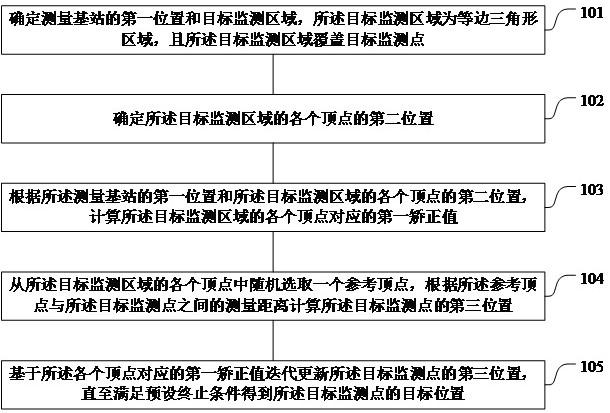
[0084] Refer figure 1 It shows a specific step of a monitoring method according to an embodiment of the present invention.
[0085] Step 101 determines the first position and target monitoring area of the measurement base station, the target monitoring area is an equilateral triangular area, and the target monitoring area covers the target monitoring point.
[0086] Step 102 determines the second position of each vertex of the target monitoring area.
[0087] Step 103, calculate the first correction value corresponding to the respective vertices of the target monitoring region according to the first position of the measurement base and the respective vertices of the target monitoring region.
[0088] Step 104: A reference vertex is randomly selected from the respective vertices of the target monitoring area, and the third position of the target monitoring point is calculated from the measurement distance between the reference vertices and the target monitoring point.
[0089] St...
Embodiment 2
[0149] Refer figure 2 It shows a structural diagram of a device according to an embodiment of the present invention, and specific comprises:
[0150] Memory 200 is used to store computer programs.
[0151] The transceiver 210 is configured to receive and transmit data under the control of processor 220.
[0152] The processor 220 is configured to read the computer program in the memory 200 and perform the following:
[0153] A11, the first position and the target monitoring area of the base station, the target monitoring area is an equilateral triangular region, and the target monitoring area covers the target monitoring point;
[0154] A12 determines the second position of each vertex of the target monitoring area;
[0155] A13, calculates a first correction value corresponding to the respective vertices of the target monitoring area according to the first position of the measurement base station and the respective vertices of the target monitoring region;
[0156] A14, randoml...
Embodiment 3
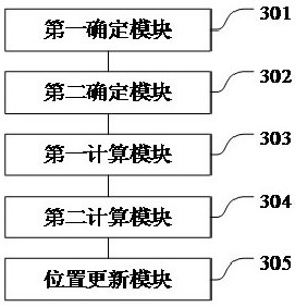
[0178] Refer image 3 Which shows a structural diagram of a monitoring apparatus according to an embodiment of the present invention comprises:
[0179] A first determining module 301 for determining a first base station is measured and the target position monitoring area, while monitoring the triangular region of the target area and the like, and the target area coverage monitoring target monitoring points;
[0180] Second determining module 302 for determining respective vertices of said second target position monitored area;
[0181] A first computing module 303, according to the second measurement position of each vertex of the first base station and the target position monitored area, calculating a first correction value of each vertex of the monitored area corresponding to the target;
[0182] The second calculating module 304 for each of the vertices from the monitoring target area in a randomly selected reference vertex, calculate the target point monitoring according to th...
PUM
 Abstract
Description
Claims
Application Information
 - R&D Engineer
- R&D Manager
- IP Professional
- Industry Leading Data Capabilities
- Powerful AI technology
- Patent DNA Extraction
Browse by: Latest US Patents, China's latest patents, Technical Efficacy Thesaurus, Application Domain, Technology Topic, Popular Technical Reports.
© 2024 PatSnap. All rights reserved.Legal|Privacy policy|Modern Slavery Act Transparency Statement|Sitemap|About US| Contact US: help@patsnap.com


