
Remote monitoring system and Internet of Things electromagnetic relay thereof

A technology of electromagnetic relay and Internet of things, applied in the direction of electromagnetic relay, electromagnetic relay details, relay, etc., can solve the problems of inability to realize cloud communication, unfavorable intelligent application, etc.

Pending Publication Date: 2022-03-04
ZHEJIANG CHINT ELECTRIC CO LTD
View PDF0 Cites 0 Cited by
  • Summary
  • Abstract
  • Description
  • Claims
  • Application Information

AI Technical Summary

Problems solved by technology

Existing relays collect voltage, current, temperature and other signals through the communication circuit unit and transmit them to the field or remote signal processing system, but the signal transmission is to use the output signal interface to connect the man-machine device externally, or use the mobile communication terminal connected by wireless communication equipment (such as mobile phones, PDAs, smart phones, etc.), display devices, etc., so that the transmitted relay signal data can only be collected by the staff on site or through the network, and cloud communication cannot be realized, which is not conducive to intelligent applications

Method used


Image

  • Remote monitoring system and Internet of Things electromagnetic relay thereof
  • Remote monitoring system and Internet of Things electromagnetic relay thereof
  • Remote monitoring system and Internet of Things electromagnetic relay thereof

Examples


Embodiment Construction

[0036] The following is attached Figures 1 to 7 The given examples further illustrate the specific implementation of a remote monitoring system and its Internet of Things electromagnetic relay of the present invention. A remote monitoring system and its IoT electromagnetic relay of the present invention are not limited to the description of the following embodiments.

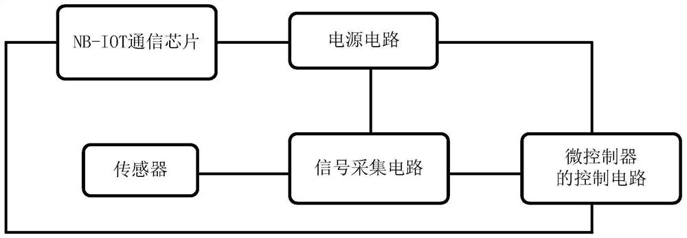
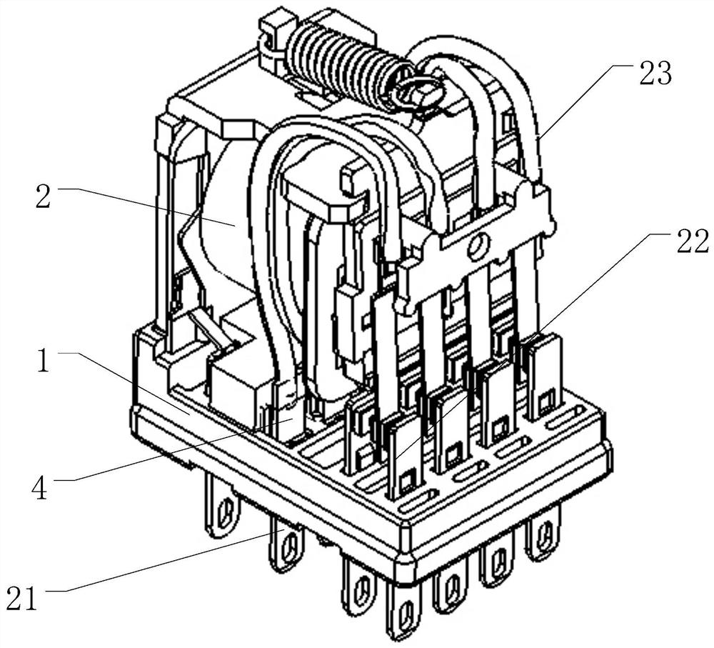
[0037] An electromagnetic relay for the Internet of Things, including a housing 1 and an electromagnetic relay body 2 disposed in the housing 1, a NB-IOT communication module and a sensor, the NB-IOT communication module is used to establish a connection with a cloud server, and the NB-IOT The communication module includes a signal acquisition circuit, a microcontroller and an NB-IOT chip. When the electromagnetic relay body 2 is powered on, the signal acquisition circuit collects the state information of the electromagnetic relay body 2 through a sensor, and the microcontroller collects and processes the state...


PUM


Abstract

The invention discloses a remote monitoring system and an Internet of Things electromagnetic relay thereof, the remote monitoring system comprises a shell, and an electromagnetic relay body, an NB-IOT communication module and a sensor which are arranged in the shell, the NB-IOT communication module is used for establishing connection with a cloud server, the NB-IOT communication module comprises a signal acquisition circuit, a microcontroller and an NB-IOT chip, and when the electromagnetic relay body is powered on, the NB-IOT chip is connected with the NB-IOT communication module. The signal acquisition circuit acquires state information of the electromagnetic relay body through the sensor, the microcontroller acquires and processes the state information of the electromagnetic relay body acquired by the signal acquisition circuit and sends the state information to the cloud server through the NB-IOT chip, and the cloud server classifies, stores, analyzes and processes the information uploaded by the NB-IOT communication module. According to the remote control system and the Internet of Things electromagnetic relay thereof, the NB-IOT communication module is connected with the cloud server, and the cloud server performs classified storage and analysis processing, so that cloud communication of the electromagnetic relay is realized, and the requirement of intelligent use is met.

Description

technical field [0001] The invention relates to a switch device, in particular to a remote monitoring system and an electromagnetic relay of the internet of things. Background technique [0002] An electromagnetic relay is an electronic control device used in an automatic control circuit. It has an electromagnetic system (also known as an input circuit) and a contact system (also known as an output circuit). Its working principle is to use a smaller current and a lower voltage to An automatic switch that controls larger currents and higher voltages. Existing relays collect voltage, current, temperature and other signals through the communication circuit unit and transmit them to the field or remote signal processing system, but the signal transmission is to use the output signal interface to connect the man-machine device externally, or use the mobile communication terminal connected by wireless communication equipment (such as mobile phones, PDAs, smart phones, etc.), disp...

Claims


Application Information

Patent Timeline
IPC IPC(8): G05B19/042G01D21/02H01H47/00H01H50/00G08C17/02
CPCG05B19/0428G01D21/02H01H47/001H01H50/00G08C17/02G05B2219/2612
Inventor 王景凯于雪峰金福黄辉忠
Owner ZHEJIANG CHINT ELECTRIC CO LTD
Learn More