Aviation piston engine ground test bed system

A technology of piston engine and test bench, which is applied in engine testing, machine/structural component testing, measuring devices, etc., can solve the problems of test bench dumping, high temperature environment, and test bench structural damage, etc., to ensure accuracy, Improve the effectiveness of detection results

Pending Publication Date: 2022-03-04
CIVIL AVIATION UNIV OF CHINA
View PDF6 Cites 0 Cited by
  • Summary
  • Abstract
  • Description
  • Claims
  • Application Information

AI Technical Summary

Problems solved by technology

[0003] Chinese invention patent CN2020112581858 discloses a test bench and method for a UAV piston engine with a clutch, which belongs to the field of UAVs; including a frame body, an engine mounting plate, a starting motor mounting plate, a starting motor servo control cabinet, and a starting motor servo mechanism; the frame body is a truss structure with unequal heights at both ends, which is used to support the entire device; the starter motor servo control cabinet is installed at the bottom of the frame body, and the starter motor servo mechanism is remotely controlled through cables and control handles; The starter motor mounting plate is horizontally fixed on the lower end of the frame body through the starter motor servo mechanism, and is used to install the starter motor assembly; the engine mounting plate is horizontally fixed on the higher end of the frame body, and is used to install the piston engine; the piston engine test bench Trial trouble, poor versatility, poor stability
[0004] At the same time, when installing the aviation piston engine, the positioning accuracy of the engine is required to be high, and the adaptability is poor. It is impossible to test multiple aviation piston engines, and the vibration of the aviation piston engine during the test run will affect the detection results. , a high temperature environment will be generated when the engine is started, and it will also cause damage to the internal structure of the test bench
[0005] At the same time, when the propeller speed is adjusted, the airspeed of the engine will be changed, which will cause damage to the balance of the test bench, mainly including that when the airspeed increases, the test bench will fall backwards, and when the airspeed is too fast, due to the excessive weight of the front end of the piston engine. Assembly caused test bench to tip forward

Method used


Image

  • Aviation piston engine ground test bed system
  • Aviation piston engine ground test bed system
  • Aviation piston engine ground test bed system

Examples


no. 1 example

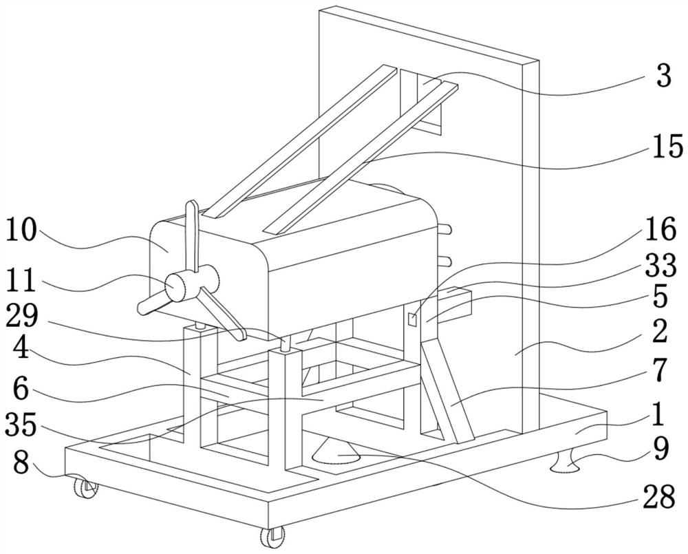
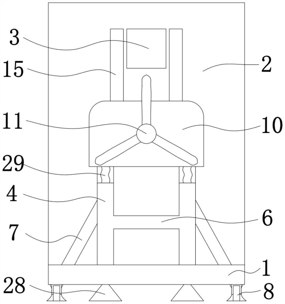
[0026] like figure 1 and figure 2 As shown, an aviation piston engine ground test platform system includes a base 1, the top of the base 1 is provided with a baffle 2, the baffle 2 is located at the back of the middle of the base 1, and the top of the base 1 is respectively provided with a front bracket 4 and a rear bracket 5. A beam 35 is provided between the front bracket 4 and the rear bracket 5. The beam 35 is used to ensure the stability between the front bracket 4 and the rear bracket 5. The front bracket 4 is located at the end of the rear bracket 5 away from the baffle 2. The rear bracket 5. A buffer bellows 19 is provided at the top, and the top of the buffer bellows 19 is provided with an engine 10. The buffer bellows 19 shocks and buffers the engine 10 during use to ensure the stability of the engine 10 during the test run. The top of the engine 10 is provided with The connecting belt 15 is used for bolt pulling the top of the engine 10 to ensure the stability of ...

no. 2 example

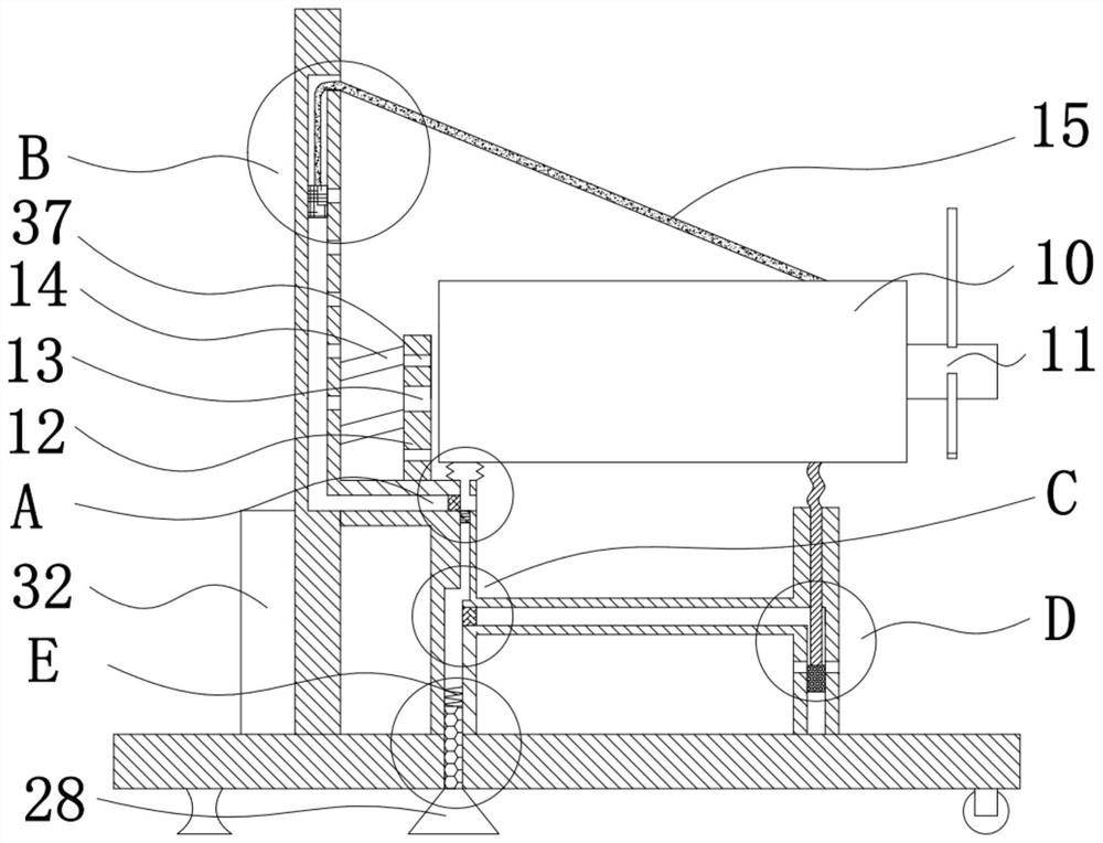
[0036] like Figure 3-7 The shown ground test platform system for aero piston engine, in actual use, when the air speed of the engine 10 decreases, the wind speed generated by the propeller 11 on one side of the engine 10 decreases, so that the engine 10 will be pulled down under the action of its own weight. The belt 15 is connected, and when the wind speed generated by the propeller 11 on the side of the engine 10 increases, the propeller 11 end of the engine 10 will rise upward to cause the base 1 or the baffle 2 to overturn, and at the same time, the engine 10 will generate heat when it is working. It is ensured that the base 1 and the baffle 2 will not be damaged when the airspeed of the engine 10 changes during use, and the generated wind can be prevented from being discharged at will, causing environmental pollution and damage, and improving the performance of the engine 10 and the base 1 and baffle 2. Cooling effect, the aero-piston engine ground test platform system a...

no. 3 example

[0052] It can be seen from the second embodiment that in actual use, the engine 10 will vibrate when it is working, and the buffer bellows 19 will have a good shock-absorbing and buffering effect on the vibration of the engine 10. The gas will be squeezed and expanded synchronously with the vibration of the engine 10, and when the engine 10 vibrates, it will also drive the vibration of the base 1, thereby causing damage to the operator and the top device. In order to solve the above problems, ensure that when the engine 10 vibrates Each part is still in an absolutely stable state. When the aviation piston engine ground test platform system is actually used: due to the relative distribution of the second air passage 18 and the third air passage 23, the air inlet 16 and the first air passage 17 are directly distributed. , so when each device is in a stable state and the engine 10 is working stably, the engine 10 will move downward due to its internal turbine structure. 19 exerts...


PUM


Abstract

The invention belongs to the technical field of test bed, and particularly relates to an aviation piston engine ground test bed system which comprises a base, a baffle is arranged at the top of the base, a front support and a rear support are arranged at the top of the base, a cross beam is arranged between the front support and the rear support, and the front support is located at the end, away from the baffle, of the rear support. A buffering corrugated pipe is arranged at the top of the rear support, an engine is arranged at the top of the buffering corrugated pipe, a connecting belt is arranged at the top of the engine, and a center console is arranged on the side, away from the engine, of the baffle. One end, far away from the baffle plate, of the rear bracket is provided with an air inlet, the other end of the rear bracket is provided with a connecting beam, and the other end of the connecting beam is fixedly connected with the baffle plate. And meanwhile, resonance of the base and the engine is avoided when the engine vibrates, and the operation comfort and the durability of the device are improved.

Description

technical field [0001] The invention belongs to the technical field of test stands, in particular to a ground test stand system for an aviation piston engine. Background technique [0002] Aero-engine is a thermal power device with high technical difficulty, complex working conditions, harsh maintenance requirements and high development and use costs. It has a very complex structure and plays a vital role in the reliability, safety and performance of the aircraft operation. In order to ensure flight safety, the aero-engine must be regularly tested and tested during the life of the aero-engine. The performance of the engine is good or bad. [0003] Chinese invention patent CN2020112581858 discloses an unmanned aerial vehicle piston engine test bench and method with a clutch, belonging to the field of unmanned aerial vehicles; including a frame body, an engine mounting plate, a starting motor mounting plate, a starting motor servo control cabinet, and a starting motor servo ...

Claims


Application Information

Patent Timeline
Patent Type & Authority Applications(China)
IPC IPC(8): G01M15/02
CPCG01M15/02
Inventor 徐琛刘畅白会新高名扬聂尔冰郝晓红武佳昱
Owner CIVIL AVIATION UNIV OF CHINA
Why Eureka
Try Eureka