Method for measuring and adjusting axial clearance of thrust bearing of shaft seal type nuclear main pump

A thrust bearing and axial clearance technology, applied in mechanical clearance measurement, measuring device, mechanical measuring device, etc., can solve the problems of inability to check the contact situation, large size of parts, complicated installation steps, etc.

Pending Publication Date: 2022-03-04
HARBIN ELECTRIC POWER EQUIP
View PDF0 Cites 0 Cited by
  • Summary
  • Abstract
  • Description
  • Claims
  • Application Information

AI Technical Summary

Problems solved by technology

The traditional dummy shaft adjustment process has complicated installation steps, uses large and many parts, and has high requirements for the site. The adjustment method requires a special motor support installation platform and large hydraulic lifting equipment. The process is used for thrust bearings. When there is an axial gap, obvious quality defects will occur, including: the thrust plate is not installed in place but cannot be directly observed, and the contact between the lower bearing chamber and the upper bearing chamber cannot be checked after the lower bearing chamber is installed in the motor support, resulting in the thrust plate and the thrust The pad gap is not controlled and accurate measurement results cannot be obtained, and even the gap between the thrust plate and the thrust pad needs to be readjusted. The gap between the thrust plate and the thrust pad is too large or too small, which will lead to abnormal oil temperature and oil pressure of the thrust bearing, excessive vibration of the main pump, serious damage to the thrust bearing, and even more serious accidents in nuclear power plants

Method used


Image

  • Method for measuring and adjusting axial clearance of thrust bearing of shaft seal type nuclear main pump
  • Method for measuring and adjusting axial clearance of thrust bearing of shaft seal type nuclear main pump
  • Method for measuring and adjusting axial clearance of thrust bearing of shaft seal type nuclear main pump

Examples


Embodiment Construction

[0031] Such as figure 1 As shown, a method for measuring and adjusting the axial clearance of the thrust bearing of the shaft-sealed nuclear main pump adopts the pressure plate clamping the thrust plate and the dial indicator to measure and accurately measure and adjust the axial clearance of the thrust bearing. The method includes the following steps:

[0032] 1) Complete the pressure plate assembly: place the upper pressure plate 6 on the thrust plate 13, place the mandrel 3 on the upper pressure plate 6, install the lower pressure plate 11 on the thrust plate 13, and use the second hex head bolt 7. Screw through the lower pressure plate 11 and the mandrel 3, place the measuring disc 2 on the mandrel 3, install and tighten the first hex head bolt 1;

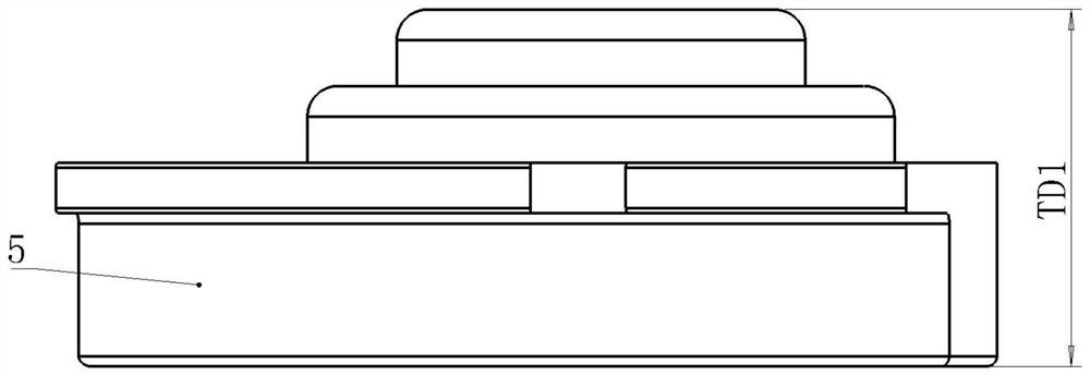
[0033] 2) if figure 2 As shown, measure whether the height TD1 of all main thrust tile assemblies 5 satisfies 69.99mm≤TD1≤70mm, if the height TD1 does not meet the requirements, the existing main thrust tile assemblies 5 shoul...


PUM

PropertyMeasurementUnit
Thicknessaaaaaaaaaa

Abstract

The invention relates to a method for measuring and adjusting the axial clearance of a thrust bearing of a shaft seal type nuclear main pump, which adopts a mode of clamping a thrust disc by a pressure disc and measuring by a dial indicator so as to accurately measure and adjust the axial clearance of the thrust bearing, and comprises the following steps of: completing the assembly of the pressure disc: placing an upper pressure disc (6) on the thrust disc (13); the mandrel (3) is placed on the upper pressure disc (6), the lower pressure disc (11) is installed on the thrust disc (13), the second hexagon-headed bolt (7) penetrates through the lower pressure disc (11) to be tightened with the mandrel (3), the measuring disc (2) is placed on the mandrel (3), and the first hexagon-headed bolt (1) is installed and tightened. According to the invention, the heights of the thrust pads are basically consistent and the gaps between the thrust pads and the thrust disc meet the requirements, so that the problems that the axial movement range of the thrust disc is too large or too small and the gaps between the thrust pads and the thrust disc are different are solved.

Description

Technical field: [0001] The invention relates to a method for measuring and adjusting the axial clearance of the thrust bearing of a shaft-sealed nuclear main pump. Background technique: [0002] The thrust bearing is the main component of the shaft-sealed nuclear main pump in nuclear power plants, and is also a key component of the nuclear main pump. The control of the axial clearance of the thrust bearing is particularly important for the normal operation of the shaft-sealed nuclear main pump and the localization of the main pump manufacturing technology. The precise adjustment of the thrust bearing axial clearance has always been a technical problem. The traditional dummy shaft adjustment process has complicated installation steps, uses large and many parts, and has high requirements for the site. The adjustment method requires a special motor support installation platform and large hydraulic lifting equipment. The process is used for thrust bearings. When there is an ax...

Claims


Application Information

Patent Timeline
IPC IPC(8): G01B5/14B25B11/00
CPCG01B5/146B25B11/00Y02E30/30
Inventor 杜帆黄秀波赵环宇谢宝萍王文彬王志威王均馗梁建彬曹海文
Owner HARBIN ELECTRIC POWER EQUIP
Why Eureka
Try Eureka