
Tire turning angle analysis method based on gyroscope and steering wheel turning angle

A technology of steering wheel angle and analysis method, applied in the field of automatic driving, can solve problems such as large amount of calculation, high equipment cost, tire angle error, etc., and achieve the effect of reducing memory footprint, small calculation volume, and high stability

Active Publication Date: 2022-03-04
SHANGHAI ALLYNAV TECH CO LTD
View PDF9 Cites 2 Cited by
  • Summary
  • Abstract
  • Description
  • Claims
  • Application Information

AI Technical Summary

Problems solved by technology

[0002] Autonomous driving requires real-time monitoring of vehicle driving information, including real-time monitoring of tire rotation angles. Accurate control of tire rotation angles can accurately control vehicle steering. Existing technologies are calculated by steering wheel rotation angles and vehicle transmission ratios. In practical applications There is a problem in the process: due to the aging and wear of the vehicle during the use of the vehicle, the vehicle has the problem of pressure relief and clearance. The problem of pressure relief and clearance of the vehicle causes the relationship between the steering wheel angle and the tire angle to not correspond. At this time, through the steering wheel angle There is a large error in the tire rotation angle obtained with the gear ratio, which is sometimes fatal;
[0003] Aiming at the problem that there is a large error in the tire rotation angle obtained from the steering wheel rotation angle and the transmission ratio, it can also be detected by the Hall angle sensor, but the installation of the Hall angle sensor is complicated, the cost is high, and the loss is large. At the same time, as a sensor, it is difficult to solve the problem. The problem of large errors caused by environmental influences; how to obtain accurate tire corners at low cost is an urgent problem to be solved;
[0004] Based on the above problems, the Chinese invention patent preview path tracking calculation method and tracking calculation module, the patent number is CN202010174649.0 patent discloses a preview path tracking calculation method for the path tracking preview model of automatic driving vehicles, including obtaining Autopilot vehicle system delay; in the global path based on the uniform acceleration model extrapolation to calculate the vehicle position after the system delay; calculate the preview error; calculate the tire angle according to the relationship between the preview error and the tire angle, and calculate the steering wheel angle according to the tire angle , the steering wheel angle is sent to the chassis CAN to perform steering wheel angle control; a preview path tracking calculation module for automatic driving vehicles is also disclosed, which reduces the preview path tracking calculation error caused by system delay, and ensures the safety and reliability of the vehicle. Driving provides the basis; firstly, the invention cannot completely overcome the system delay and error problems, it depends on the progress of hardware, and at the same time, it has a large amount of calculation, complex calculation, and consumes a lot of resources;
[0005] Chinese invention patent A method and system for dynamically measuring tire rotation angle through visual means, patent number CN201911413760.4 proposes to dynamically measure tire rotation angle based on visual means, install a synchronous steering rotating disc on the vehicle tire, and install a camera above the rotating disc module, and the camera module is facing the rotating disk, the image of the rotating disk is collected through the camera module during measurement, the image is input to the image processing module to obtain the steering position of the rotating disk, and the angle module obtains the angle of rotation of the vehicle tires according to the steering position, through the image Accurate tire angles are processed, which also has the problems of high equipment costs and complicated calculations;
[0006] A Chinese invention patent for a detection device for the synchronous rate of tire rotation angles. Patent No. CN201910379753.0 proposes a device for detecting the synchronous rate of tire rotation angles. The sensor assembly used to receive signals, the bracket fixed at the end of the sensor assembly, and the two brackets The first connecting shaft at the end, the shock absorbing assembly connected with the sensor assembly, the connecting rod member hinged at the other end of the shock absorbing assembly, and the suction cup assembly fixedly arranged at the end of the connecting rod member; the sensor assembly includes a sensor member and a sensor member fixedly arranged on the sensor member The fixed structure on the top; the end of the sensor component is fixedly connected to the bracket, and the fixed structure is fixedly connected to one end of the shock absorber assembly by bolts, and the error in the tire rotation angle obtained based on the transmission ratio is solved by detecting the synchronization rate, but it also cannot solve the problem of vehicle running for a period of time. Finally, the pressure relief and clearance problems of the vehicle lead to the problem of calculation deviation of the tire rotation angle due to the mismatch between the steering wheel angle and the tire rotation angle

Method used


Image

  • Tire turning angle analysis method based on gyroscope and steering wheel turning angle
  • Tire turning angle analysis method based on gyroscope and steering wheel turning angle
  • Tire turning angle analysis method based on gyroscope and steering wheel turning angle

Examples


Embodiment 1

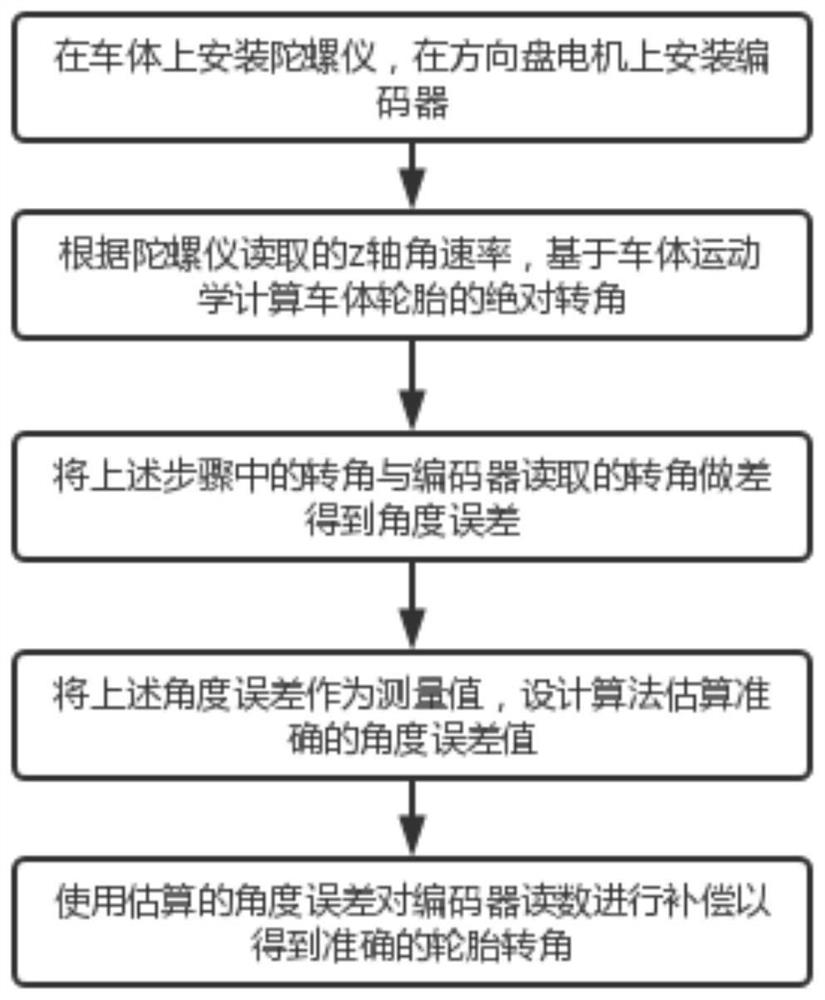
[0054] A tire rotation angle analysis method based on gyroscope and steering wheel angle, characterized in that: the analysis method includes:

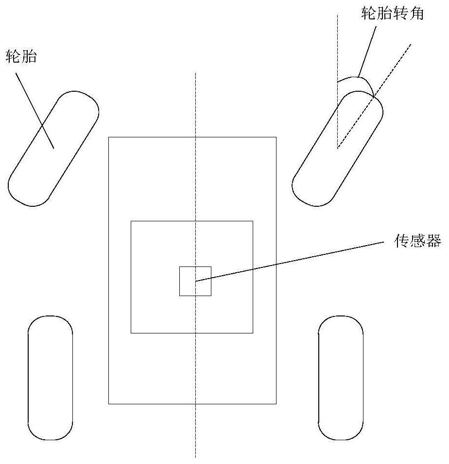
[0055] S100: install a gyroscope on the car body, read the Z-axis angular rate of the gyroscope, and calculate the relative rotation angle of the wheel relative to the car body based on the kinematics of the car body;

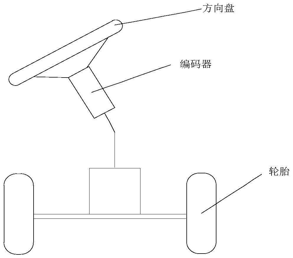
[0056] S200: Set an encoder on the steering wheel motor, and read the encoder to obtain the steering wheel angle;

[0057] S300: Obtain the angle error between the relative rotation angle and the steering wheel rotation angle;

[0058] S400: Filter the angle error through a Kalman filter algorithm to obtain an optimal value of the angle error;

[0059] S500: Compensate the steering wheel angle according to the optimal value of the angle error calculated in step S400 to obtain the final tire angle, and output the tire angle.

[0060] On the one hand, the Z-axis angular rate read by the gyroscope is the yaw angular rat...


PUM


Abstract

The invention discloses a tire turning angle analysis method based on a gyroscope and a steering wheel turning angle, and belongs to the technical field of automatic driving. The relative rotation angle of the wheels relative to the vehicle body is calculated based on the vehicle body kinematics through the gyroscope, and the encoder is arranged on the steering wheel motor and is read to obtain the steering wheel rotation angle; according to the method, errors of a steering wheel rotation angle and a relative rotation angle are unified through an angle error, then filtering is carried out based on a Kalman filtering algorithm, an optimal value of the angle error is obtained, and therefore the accurate tire rotation angle is obtained, the tire rotation angle can be accurately output only through one gyroscope, and accurate output is obtained under the condition of low cost; through the algorithm, the tire rotation angle can be output in real time, the calculation volume is small, the stability is high, errors are small, additional storage space for data storage is not needed, and the occupied space of a memory is reduced.

Description

technical field [0001] The invention relates to the technical field of automatic driving, in particular to a tire rotation angle analysis method based on a gyroscope and a steering wheel angle. Background technique [0002] Autonomous driving requires real-time monitoring of vehicle driving information, including real-time monitoring of tire rotation angles. Accurate control of tire rotation angles can accurately control vehicle steering. Existing technologies are calculated by steering wheel rotation angles and vehicle transmission ratios. In practical applications There is a problem in the process: due to the aging and wear of the vehicle during the use of the vehicle, the vehicle has the problem of pressure relief and clearance. The problem of pressure relief and clearance of the vehicle causes the relationship between the steering wheel angle and the tire angle to not correspond. At this time, through the steering wheel angle There is a large error in the tire rotation a...

Claims


Application Information

Patent Timeline
Patent Type & Authority Applications(China)
IPC IPC(8): B60W40/00B60W50/00B60W60/00
CPCB60W40/00B60W50/00B60W60/00B60W2050/0002
Inventor 具大源李晓宇李奕成
Owner SHANGHAI ALLYNAV TECH CO LTD
Learn More