
Lead cathode plate spot welding device

A spot welding device and cathode plate technology, applied in the direction of electrode characteristics, welding equipment, resistance welding equipment, etc., can solve the problems of large crystal particles, insufficient force-bearing surface, tearing of cathode plate solder joints, etc., to increase the contact area, The stability is guaranteed and the effect of reducing the gravity difference

Pending Publication Date: 2022-03-04
SHUI KOU SHAN NONFERROUS METALS LTD
View PDF0 Cites 0 Cited by
  • Summary
  • Abstract
  • Description
  • Claims
  • Application Information

AI Technical Summary

Problems solved by technology

[0004] The crystallization of the precipitated lead produced by the existing technology in the range above and below the spot welding horizontal line is not ideal, and the ports on both sides of the lead skin do not form a good and dense fusion body, which leads to the increase of the electrolysis current and electrolysis cycle. The increase of the lead sheet is quite obvious at the site, which seriously affects the production
According to the physical analysis of the dropped cathode sheet: First, because the liquid level of the electrolyte in the electrolytic cell has reached the upper limit, the position of the solder joint floats 10mm close to the liquid level of the electrolyte, and the area of ​​the joint surface below the liquid level is small, resulting in stress Second, due to the grinding of the spot welding head in the manufacturing process of the cathode sheet, the solder joints of the cathode sheet are torn and loose in the later stage, resulting in uneven electric field, and large and irregular crystal particles precipitated after segregation

Method used


Image

  • Lead cathode plate spot welding device
  • Lead cathode plate spot welding device
  • Lead cathode plate spot welding device

Examples


Embodiment Construction

[0036] The present invention will be described in detail below in conjunction with specific embodiments. The following examples will help those skilled in the art to further understand the present invention, but do not limit the present invention in any form. It should be noted that those skilled in the art can make several modifications and improvements without departing from the concept of the present invention. These all belong to the protection scope of the present invention.

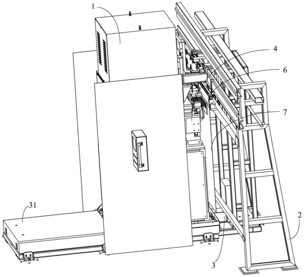
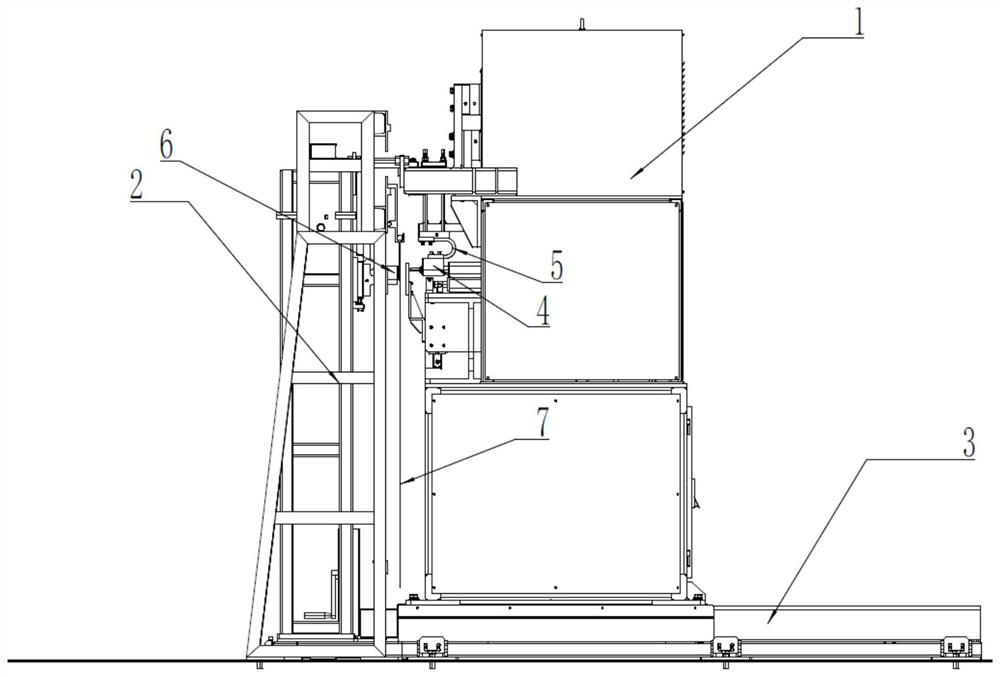
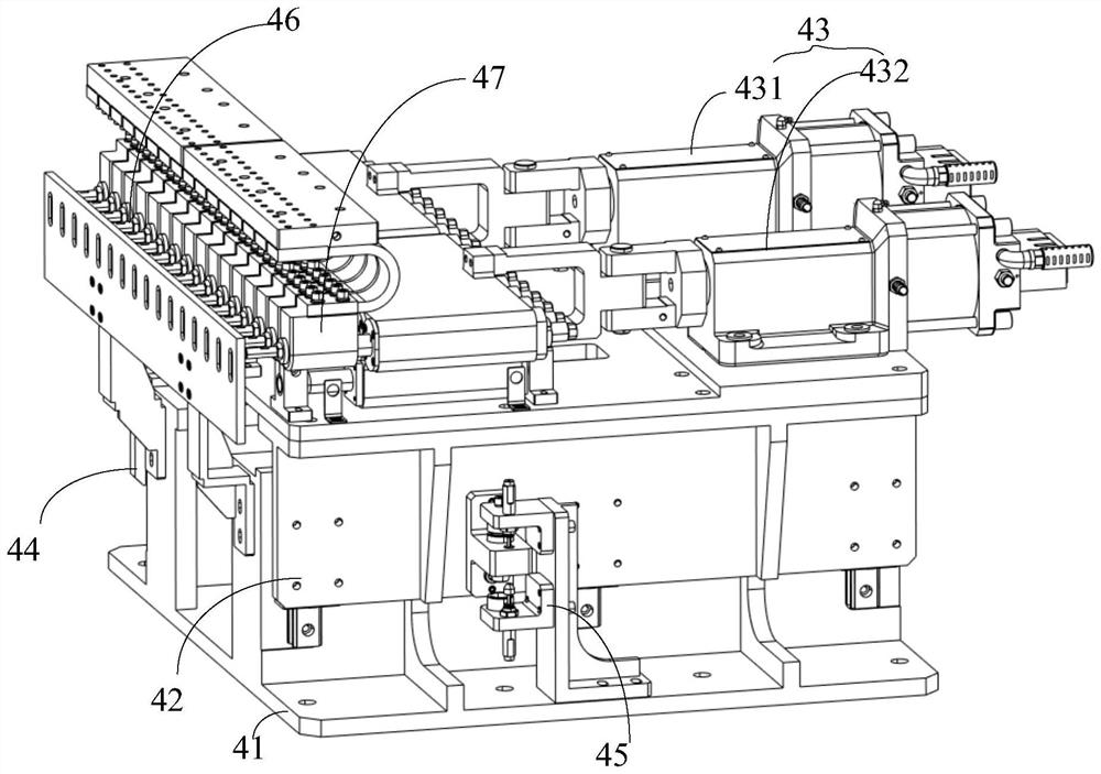
[0037] refer to Figure 1 to Figure 5

[0038] The present invention provides a lead cathode plate 7 spot welding device, comprising: a frame 2, a lower electrode 6, a cathode plate 7, a hand screw mechanism 3 and a spot welding mechanism 4, the frame 2 is used to provide a fixed installation position , the lower electrode 6 is fixed on the frame 2; the cathode plate 7 is arranged on the side of the lower electrode 6 away from the frame 2 opposite to the lower electrode 6; the hand crank The scr...


PUM


Abstract

The invention discloses a lead cathode plate spot welding device which comprises a rack, a lower electrode, a cathode plate, a hand-cranking lead screw mechanism and a spot welding mechanism. The cathode plate and the lower electrode are oppositely arranged on one side, far away from the rack, of the lower electrode; the hand-cranking lead screw mechanism comprises a movable guide rail arranged on one side of the machine frame. The spot welding mechanism is arranged on the movable guide rail, and the hand-cranking lead screw mechanism drives the spot welding mechanism to be close to or away from the rack along the movable guide rail. The spot welding mechanism comprises a moving seat arranged on the movable guide rail, a base arranged on the moving seat, a horizontal air cylinder horizontally arranged on the base, a vertical air cylinder arranged below the base, guiding pieces vertically arranged on the two sides of the base, a spot welding machine fixedly arranged on the moving seat and a welding head set arranged at the output end of the horizontal air cylinder. Double-row spot welding is designed, so that the reliability of the large-pole-plate lead electrolysis process is improved, the overall stress stability of the cathode piece is improved, and the conductive uniformity of the cathode piece in the electrolysis process is improved.

Description

technical field [0001] The invention relates to the technical field of lead refining production, in particular to a lead cathode plate spot welding device. Background technique [0002] The manufacture of cathode plates in the large plate electrolysis process of lead refining is a key part of the production process. After cutting, folding, assembling copper rods, and embossing, the lead sheets will enter the spot welding machine for single-row spot welding. Lead smelting In the process of the electrolytic tank, the cathode sheet has dropped poles. The inspection found that the crystallization of the precipitated lead at the welding position is not dense enough, and the fusion area is not enough. [0003] Lead has the metal physical properties of low melting point and strong ductility. Among them, non-ferrous metal welding methods include laser welding, ultrasonic welding, resistance welding, etc., and resistance welding is divided into spot welding, projection welding, seam ...

Claims


Application Information

Patent Timeline
IPC IPC(8): B23K11/11B23K11/30B23K11/31B23K11/36
CPCB23K11/11B23K11/30B23K11/31B23K11/36
Inventor 范振宇廖丽柯廖舟郭飞刘四毛周长福
Owner SHUI KOU SHAN NONFERROUS METALS LTD
Learn More