Internal rapid drainage method for building
A rapid and architectural technology, applied in construction, water supply installations, indoor sanitary pipeline installations, etc., can solve problems affecting the sleep quality of neighbors, loud noise, pipeline blockage, etc., to improve drainage efficiency, reduce noise pollution, prevent The effect of clogging
- Summary
- Abstract
- Description
- Claims
- Application Information
AI Technical Summary
Problems solved by technology
Method used
Image
Examples
Embodiment 1
[0049] Such as Figure 6 As shown, a method for rapid internal drainage of buildings; including the following steps:
[0050] S1: Connect the casing to the downpipe, the downpipe is connected to the drum inside the casing, and the bottom of the casing is connected to the drainpipe;
[0051] S2: start the servo motor, the servo motor drives the worm gear and the worm to rotate;
[0052] S3: The worm indirectly drives the spiral slices to rotate in the drum to chop up large impurities;
[0053] S4: The worm gear drives the air pressure mechanism to pressurize the downpipe, and the air pressure boosts the chopped impurities out of the drum to be discharged out of the broken drain pipe; at the same time, the pressure in the housing is increased to accelerate the flow rate of the drain pipe and increase the displacement.
[0054] In step S3, larger magazines enter the drum along with the downpipe, and the servo motor drives the worm gear to rotate, and the worm gear drives the wo...
Embodiment 2
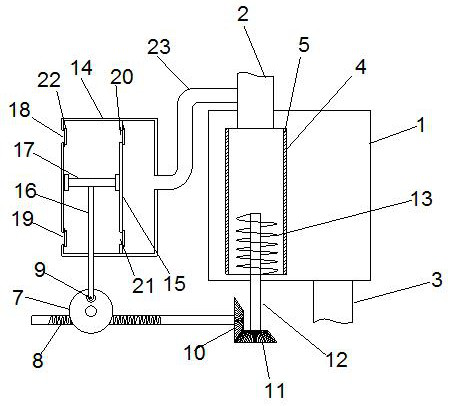
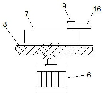
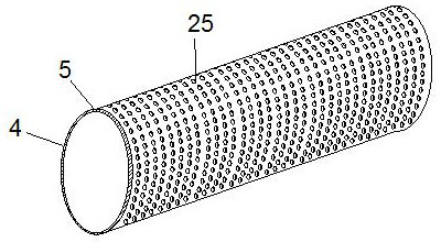
[0059] Such as Figure 1-5 As shown, a drainage device used in the internal rapid drainage method of buildings; it includes a housing 1, a downpipe 2, and a drain pipe 3; the housing 1 is provided with a drum 4, and the upper end of the drum 4 is connected to There is a downpipe 2, the inner side wall of the drum 4 is provided with a filter screen 5, and the side wall of the drum 4 is provided with a plurality of through holes 25; the housing 1 is in a sealed structure, and the bottom of the housing 1 is in contact with the drainage The tube 3 is connected; the bottom of the drum 4 is provided with a rotating shaft 12, and the rotating shaft 12 is provided with a spiral cutter 13, and the other end of the rotating shaft 12 is connected with a second gear 11, and the second gear 11 is meshed with a second gear. A gear 10, the first gear 10 is connected with a worm 8, and the worm 8 is matched and connected with a worm wheel 7 to drive the first gear 10 to rotate; One end is co...
Embodiment 3
[0062] On the basis of Embodiment 1, the air pressure mechanism includes a sealed box 14, and a partition 15 is arranged inside the sealed box 14. One side of the partition 15 is a pressurized chamber, and the other side of the partition 15 is a Gathering chamber; the inside of the pressurization chamber is provided with a piston plate 17, the piston plate 17 and the inner wall of the pressurization chamber form an airtight structure through rubber, and the piston plate 17 is slidably connected in the pressurization chamber; the piston plate 17 One side is connected with a moving rod 16, and the moving rod 16 passes through the sealing box 14 and forms a gap sliding connection with the sealing box 14.
[0063] The other end of the moving rod 16 is connected with a turning block 9, the turning block 9 is arranged on one side of the worm wheel 7, and the turning block 9 forms a rotational connection with the worm wheel 7; the turning block 9 is connected on the side wall of the w...
PUM
 Abstract
Description
Claims
Application Information
 - R&D
- Intellectual Property
- Life Sciences
- Materials
- Tech Scout
- Unparalleled Data Quality
- Higher Quality Content
- 60% Fewer Hallucinations
Browse by: Latest US Patents, China's latest patents, Technical Efficacy Thesaurus, Application Domain, Technology Topic, Popular Technical Reports.
© 2025 PatSnap. All rights reserved.Legal|Privacy policy|Modern Slavery Act Transparency Statement|Sitemap|About US| Contact US: help@patsnap.com


