Strengthening device and method for selective laser melting additive manufacturing component
A technology of laser selective melting and additive manufacturing, which is applied in the field of additive manufacturing strengthening, can solve the problems of component shape deviation, metal powder adhesion, etc., and achieve the effect of improving the dispersion
- Summary
- Abstract
- Description
- Claims
- Application Information
AI Technical Summary
Problems solved by technology
Method used
Image

Examples
Embodiment 1
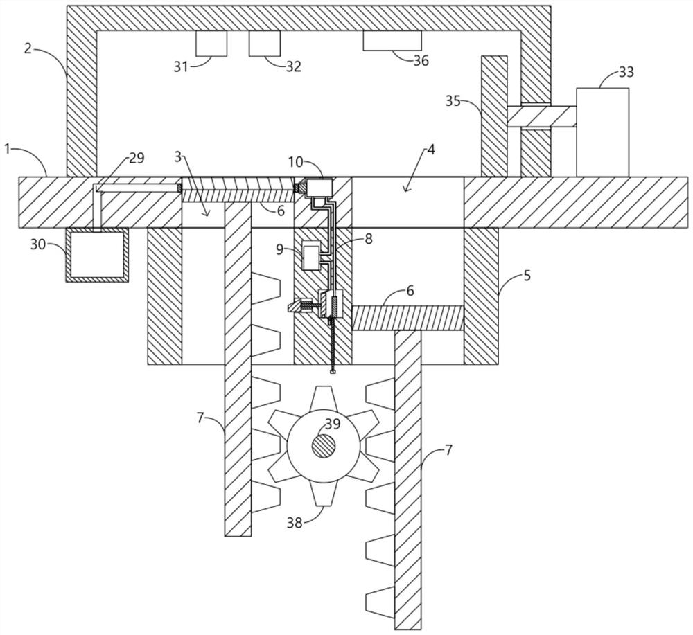
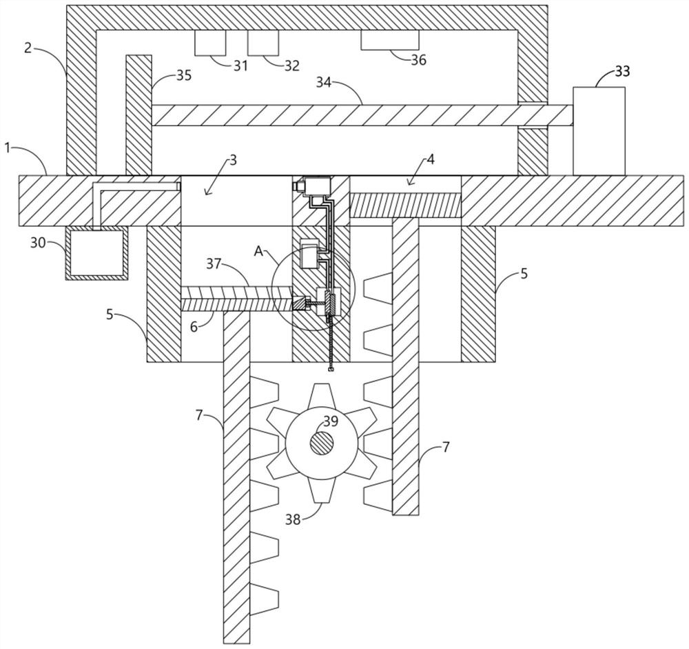
[0040]A strengthening device for laser selective melting and additive manufacturing components, including a forming platform 1 provided with a forming tank 3 and a powder storage tank 4, the forming tank 3 and the powder storage tank 4 can be square or round, and the powder storage tank 4 Metal powder is stored, and above the forming platform 1 is communicated with a working box 2 with a laser component, a powder pushing component and a heating component inside. The laser component includes a laser probe 31 for selective laser melting and a laser probe for laser peening located above the forming tank 3 32. Use the computer to perform slice discrete and scan path planning on the three-dimensional model of the component to be processed, and obtain the slice profile information scanned by the controllable laser beam. By transferring the slice profile information, the laser probe 31 is used to control the selective melting of the laser beam to emit the laser beam. The metal powder ...
Embodiment 2
[0049] Embodiment 2 improves the linkage between the sliding pallets 6 on the basis of Embodiment 1, that is, the bottom areas of the forming tank 3 and the powder storage tank 4 are the same, and the lower ends of the two sliding pallets 6 are fixedly connected with tooth plates 7, And the two toothed plates 7 are meshed with a gear 38, the gear 38 is supported and positioned by rotating the support rod 39, and by rotating the gear 38, one toothed plate 7 is slid upwards to a certain displacement, and the other toothed plate 7 is slid downwards in the same manner. Displacement, while the bottom area of the forming tank 3 and the powder storage tank 4 are the same, so that the bottom area of the forming tank 3 multiplied by the sliding height of the sliding pallet 6 in the forming tank 3 is equal to the bottom area of the powder storage tank 4 multiplied by the inside of the powder storage tank 4 The sliding height of sliding pallet 6.
Embodiment 3
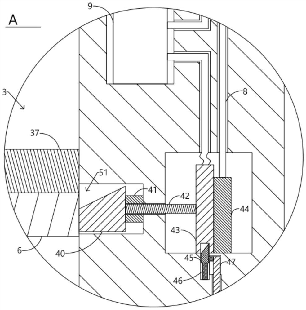
[0051] Embodiment 3 On the basis of Embodiment 1, the structure of the trigger switch is disclosed, that is, the trigger switch includes an extrusion head 40, a sliding contact block 43 and a fixed contact block 44 arranged at intervals in sequence, and the sleeve 5 is close to the forming groove 3 The lower part of one side is provided with the extrusion head sliding groove 51 for slidingly setting the extrusion head 40, and the extruding end of the extrusion head 40 and the sliding supporting plate 6 are arranged obliquely to facilitate the extrusion of the sliding supporting plate 6 to push the extrusion head 40, And the elastic push block 41 is fixedly connected between the extrusion head 40 and the inner wall of the extrusion head sliding groove 51, the extrusion head 40 stretches out under the support of the elastic push block 41 and is located below the sliding pallet 6, and the sliding pallet 6 is downward Sliding and pressing the extrusion head 40, so that the extrusio...
PUM
 Abstract
Description
Claims
Application Information
 - R&D
- Intellectual Property
- Life Sciences
- Materials
- Tech Scout
- Unparalleled Data Quality
- Higher Quality Content
- 60% Fewer Hallucinations
Browse by: Latest US Patents, China's latest patents, Technical Efficacy Thesaurus, Application Domain, Technology Topic, Popular Technical Reports.
© 2025 PatSnap. All rights reserved.Legal|Privacy policy|Modern Slavery Act Transparency Statement|Sitemap|About US| Contact US: help@patsnap.com