
Comb fitting for a combing machine

A technology for carding cloth and combing machine, applied in the direction of combing machine, fiber processing, textile and papermaking, etc., can solve the problems of increasing manufacturing error, high manufacturing cost, time-consuming and other problems, avoiding dimensional deviation, reducing The effect of a single length

Inactive Publication Date: 2010-09-22
MASCHINENFABRIK RIETER AG
View PDF13 Cites 1 Cited by
  • Summary
  • Abstract
  • Description
  • Claims
  • Application Information

AI Technical Summary

Problems solved by technology

[0009] However, these production methods have the disadvantage of high production effort and thus also high production costs
Until completion, the blank of the cloth to be manufactured must sometimes be re-clamped several times, which in turn necessarily results in time-consuming and increases the risk of manufacturing errors

Method used

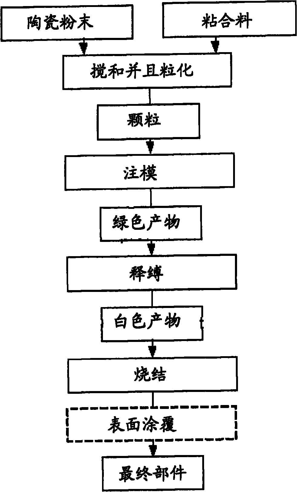

Image

  • Comb fitting for a combing machine
  • Comb fitting for a combing machine
  • Comb fitting for a combing machine

Examples


Embodiment Construction

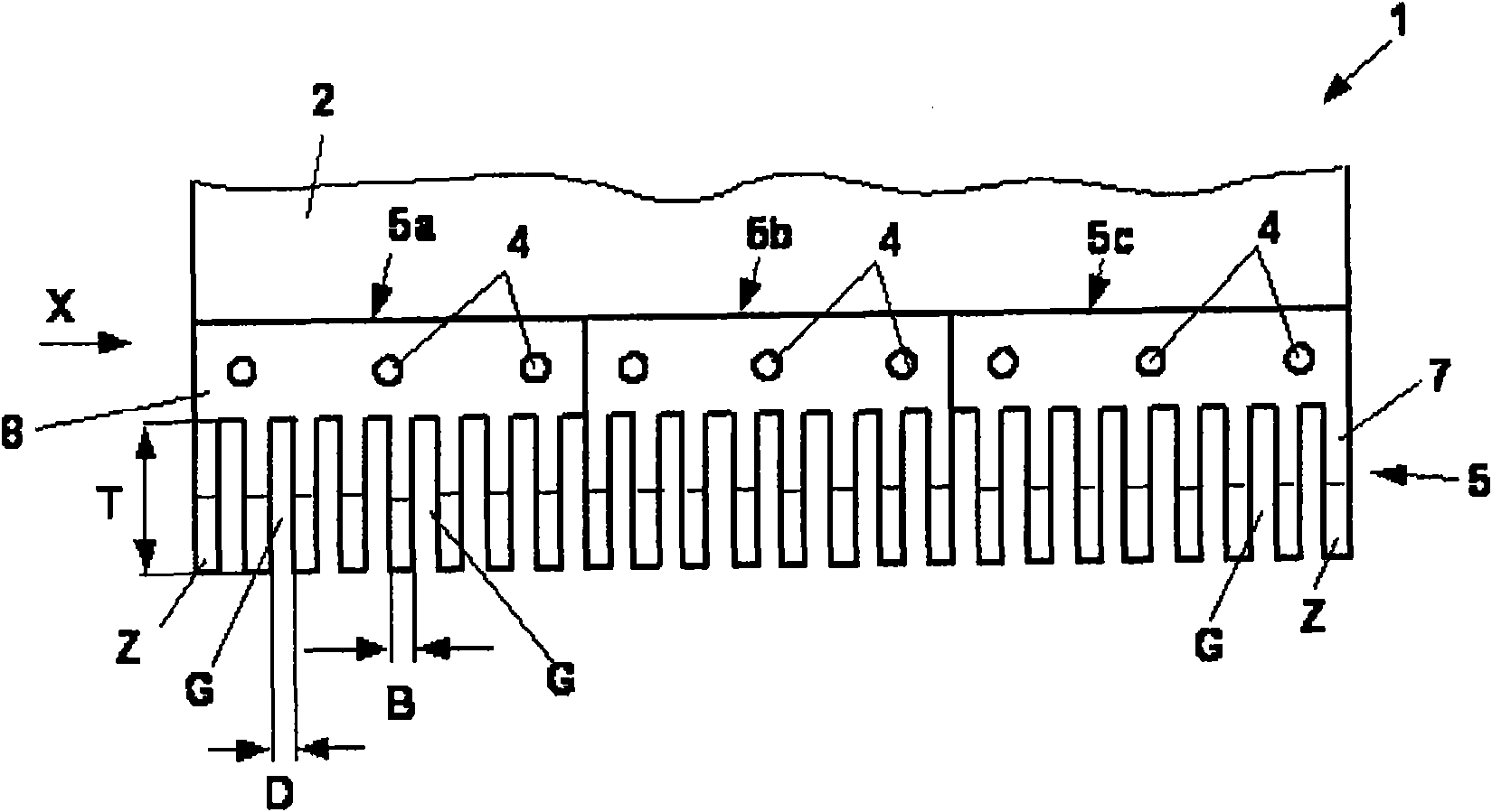
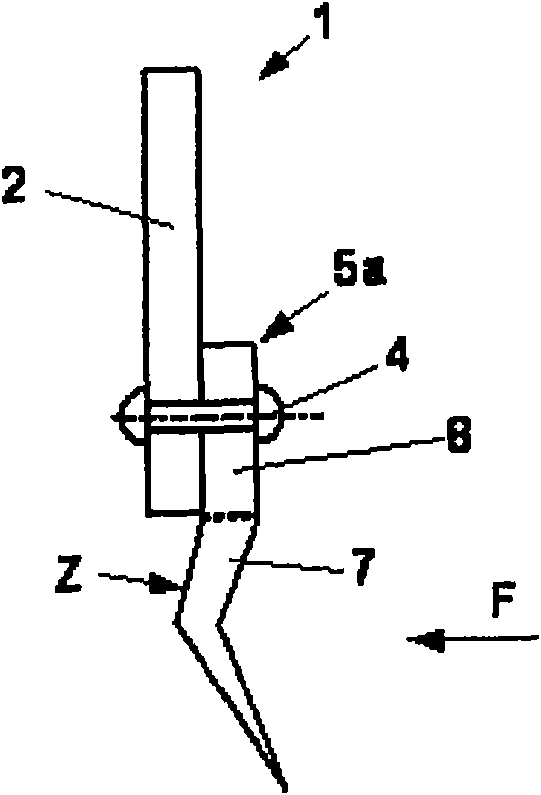
[0029] figure 1 Shows a partial view of a fixed comb 1 of a combing machine in figure 2 is shown in side view X. The fixed comb is positioned between a pair of detaching rollers and the front end of the lower nipper of the clamp assembly in its installed position, as can be seen, for example, from the published patent document DE19736582A1 figure 1 seen in.

[0030] Illustration of the fixed comb holder is omitted in this exemplary embodiment. Only frame 2 (plate) is shown, which is connected to a fixed comb holder (not shown) and to which card cloth 6 is fastened by rivets 4 . The card cloth can also be fastened to the frame 2 by other fastening means, for example by screws, or glued or welded to the frame.

[0031] as available from figure 1 It further follows that in this embodiment the carding cloths comprise three carding cloths 5a to 5c which are placed adjacent to each other and in each case of a row of teeth Z (needles) placed adjacent to each other by a rivet 4...


PUM

PropertyMeasurementUnit
widthaaaaaaaaaa

Abstract

The present invention relates to a comb fitting for a combing machine. The invention provides a method for manufacturing an integrated comb fitting (5) of a combing machine. The comb fitting is provided with a plurality of teeth (Z) which are provided adjacently and are spaced with a certain distance. The root areas (7) of the teeth form a common rod (8). For producing the comb fitting more simply with accurate dimension or even enlarging the tooth density, a final form for manufacturing the comb fitting (5) by means of power injection mold (PIM) is provided.

Description

technical field [0001] The invention relates to a method for the manufacture of an integral combing clothing for a combing machine, said combing cloth having a plurality of teeth, which are arranged adjacent to each other and at a distance, the root regions of which form a common web, and the invention also relates to a stationary comb of a combing machine with an integral carding cloth manufactured according to the method. Background technique [0002] Cloths of this type are used, for example, in circular or fixed combs of combers and for combing out the fiber material fed to them. The quality and construction of the cloth ultimately determines the quality of the finished product, which is produced on the corresponding combing machine and distributed to subsequent machines for further processing. [0003] In order to process the fed fiber bodies uniformly, it is necessary that the cloth is provided with the same geometry over its entire effective length, for example with ...

Claims


Application Information

Patent Timeline
Patent Type & Authority Applications(China)
IPC IPC(8): D01G15/84D01G19/10
CPCB22F2003/248B22F2003/241C04B2235/6022B22F2998/10C04B35/64D01G19/10B28B1/24B22F3/225B22F3/1021B22F3/24
Inventor U·斯图茨D·索默
Owner MASCHINENFABRIK RIETER AG
Learn More