Fixing structure for circuit board in junction box

A technology of fixing structure and circuit board, applied in the field of junction box, can solve the problem of loose connection between the circuit board and the inner wall of the accommodating slot, and achieve the effects of smooth installation, smooth avoidance, and uniform change in cross-sectional area.

Active Publication Date: 2022-03-01
深圳市海曼科技股份有限公司
View PDF6 Cites 0 Cited by
  • Summary
  • Abstract
  • Description
  • Claims
  • Application Information

AI Technical Summary

Problems solved by technology

[0004] In view of the above-mentioned related technologies, there is a defect that the external wiring will exert a force on the terminal post towards the notch of the accommodation slot during the wiring operation, thus easily causing the connection between the circuit board and the inner wall of the accommodation slot to loosen.

Method used


Image

  • Fixing structure for circuit board in junction box
  • Fixing structure for circuit board in junction box
  • Fixing structure for circuit board in junction box

Examples


Embodiment 1

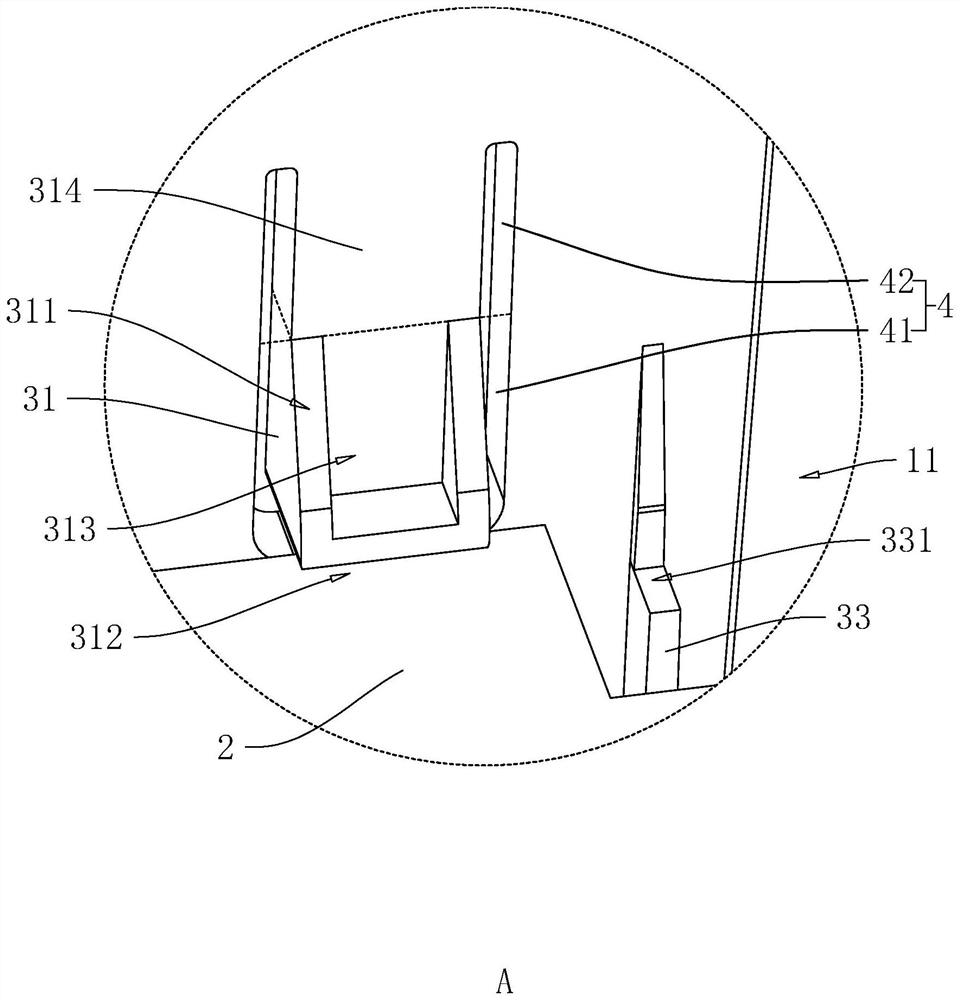
[0037] Embodiment 1, with reference to figure 1 The fixing structure for the circuit board in the junction box includes a bottom case 1, a circuit board 2 and a connection assembly 3, wherein the upper surface of the bottom case 1 is provided with an accommodating groove 11 for the circuit board 2 to be installed. In this embodiment , the setting direction of the circuit board 2 is parallel to the groove bottom direction of the accommodating groove 11, wherein the side surface of the circuit board 2 close to the groove bottom of the accommodating groove 11 is fixedly connected with a terminal, and when wiring, the external wiring will be easy. The bottom of the slot 11 is inserted on the terminal, so the circuit board 2 will be subjected to a force towards the opening of the slot 11 at this time.

[0038] refer to figure 1 with figure 2 , the connecting assembly 3 includes four blocks 31, the four blocks 31 are connected in two groups, and the two groups are integrally conn...

Embodiment 2

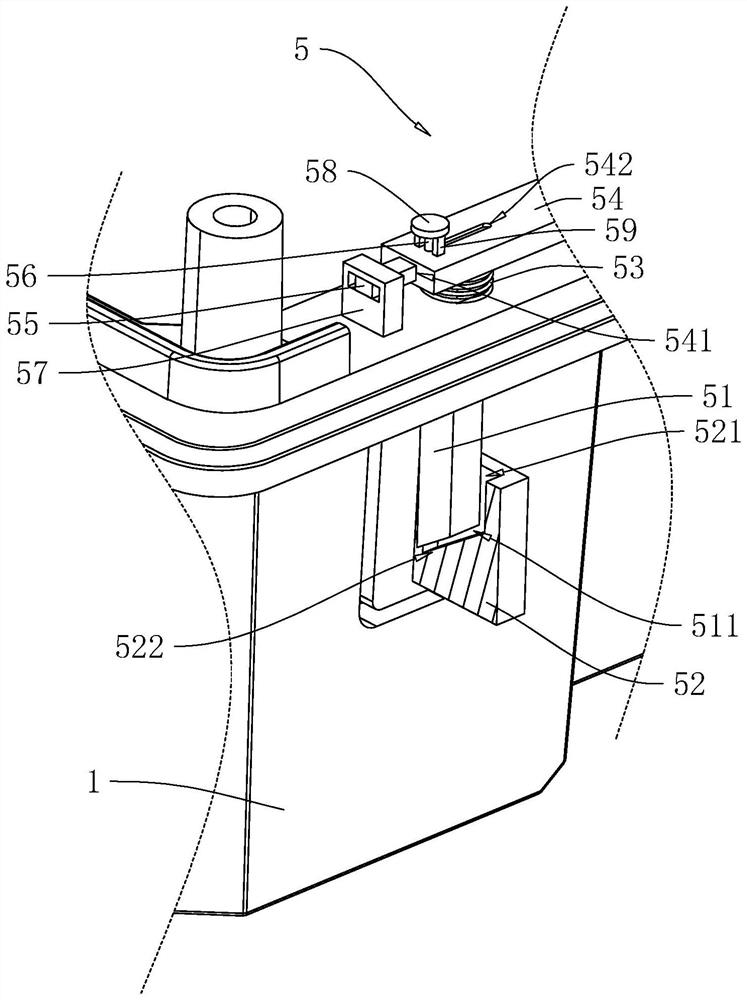
[0047] Embodiment 2, with reference to figure 1 with image 3 , the difference from Embodiment 1 is that: the bottom shell 1 is formed with a flanging at the notch of the accommodating groove 11, and the flanging is also provided with an unlocking assembly 5, specifically, the unlocking assembly 5 includes an unlocking active block 51, There are four unlocking driven blocks 52 and springs 53 and four unlocking active blocks 51 in total, and the four unlocking active blocks 51 are arranged in cooperation with the four locking blocks 31 , wherein the unlocking active blocks 51 slide through the flange of the bottom case 1 , and the end of the unlocking active block 51 close to the bottom of the accommodating groove 11 is formed with an unlocking driving surface 511 which is inclined, and the inclined height of the unlocking driving surface 511 is close to the block 31 .

[0048] refer to figure 2 with image 3The unlocking driven block 52 is integrally connected to the side ...


PUM


Abstract

The invention relates to a fixing structure for a circuit board in a junction box, which comprises a bottom shell and a circuit board, and is characterized in that the bottom shell is provided with an accommodating groove for arranging the circuit board; a connecting assembly is further included, the connecting assembly comprises a plurality of clamping blocks, the multiple clamping blocks are distributed on the inner walls of the two opposite sides of the containing groove, and the clamping blocks are provided with receding guide faces and limiting faces. When the circuit board abuts against the avoiding guide face, the clamping block can move in the direction away from the center of the containing groove. And the limiting surface is used for blocking the surface of one side, close to the opening of the accommodating groove, of the circuit board. According to the invention, when wiring operation is carried out, connection between the circuit board and the inner wall of the accommodating groove is not easy to loosen.

Description

technical field [0001] The present application relates to the field of junction boxes, in particular to a fixing structure for a circuit board in a junction box. Background technique [0002] The 86 bottom box is a specification of a junction box, and it is also an industry standard in electrical decoration. For example, a light switch at home, a box in the wall is a junction box, which is divided into a bottom box and a panel. The bottom boxes are basically the same, and the panels are different for different brands and models, but they can all be installed in the 86 bottom boxes of the same specification. [0003] In the related art, the junction box includes a bottom case, a circuit board, and a terminal. The bottom case has a circuit board and a terminal to be installed in the accommodating groove; the circuit board is fixedly connected to the inner wall of the accommodating groove by gluing. And the plane where the circuit board is located is perpendicular to the cent...

Claims


Application Information

Patent Timeline
Patent Type & Authority Applications(China)
IPC IPC(8): H02G3/08H05K7/14
CPCH02G3/081H05K7/1404
Inventor 邓伟槐龙政洪
Owner 深圳市海曼科技股份有限公司
Why Eureka
Try Eureka