Display device
A technology for a display device and a display area, which is applied in the direction of electrical components, diodes, and electric solid-state devices, and can solve problems such as emitted light interference, low light collection, and poor imaging effects
- Summary
- Abstract
- Description
- Claims
- Application Information
AI Technical Summary
Problems solved by technology
Method used
Image


Examples
Embodiment 1
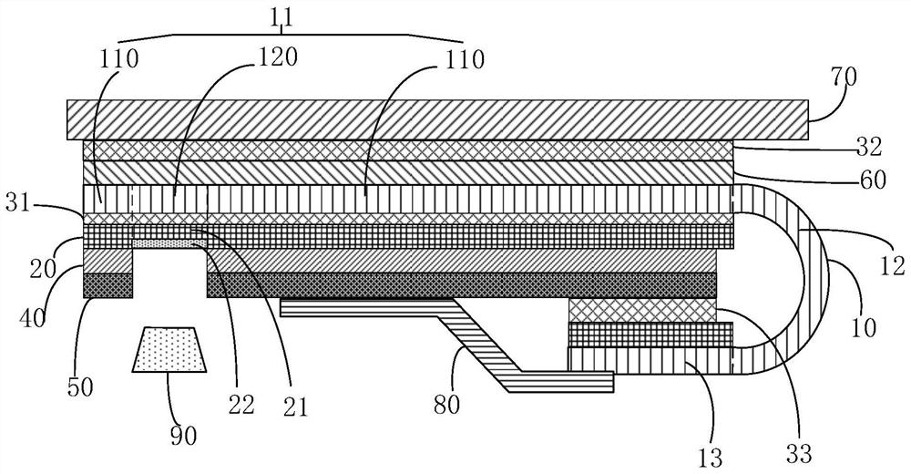
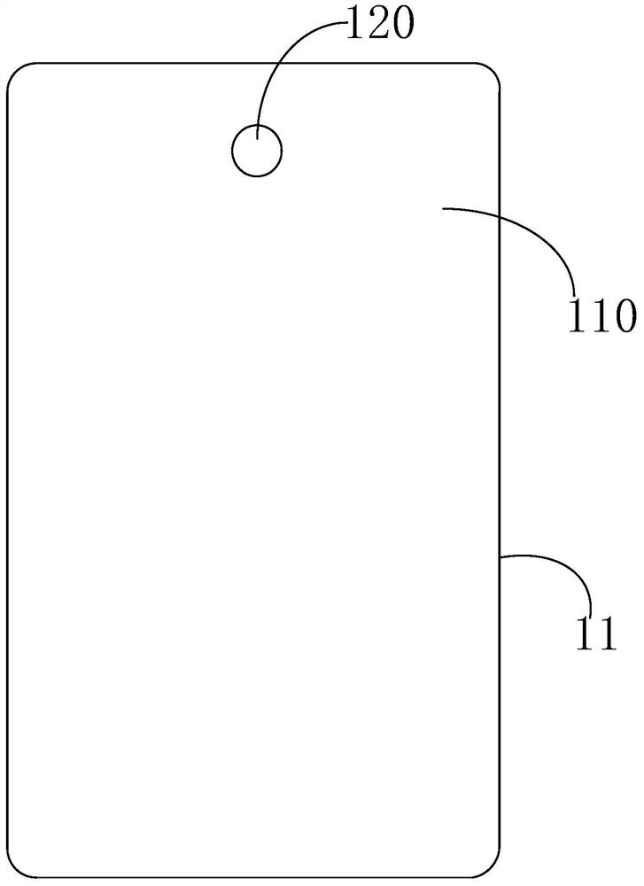
[0031] figure 1 A schematic cross-sectional view of a display device provided by an embodiment of the present invention is shown; figure 2 A schematic structural diagram of a display panel provided by an embodiment of the present invention is shown. to combine figure 1 and figure 2 As shown, the present invention provides a display device, the display device includes: a camera 90, and the camera 90 is used for lighting and imaging. The display device further includes a display panel 10 located on the light-incident side of the camera 90 . The display panel 10 is, for example, a flexible OLED display panel 10 and has a bending or folding function.
[0032] In this embodiment, the display panel 10 includes a display portion 11 , a binding portion 13 and a bending portion 12 , and the bending portion 12 is located between the display portion 11 and the binding portion 13 . The display portion 11 of the display panel 10 is provided with a plurality of light-emitting units (n...
Embodiment 2
[0053] image 3 A schematic cross-sectional view of a display device provided by an embodiment of the present invention is shown. to combine figure 2 and image 3 As shown, Embodiment 2 of the present invention provides a display device, and the structure of the display device is similar to the display device provided in Embodiment 1 of the present invention. The same or similar parts are not repeated in this embodiment. The difference is that the second backplane 22 is located on a side of the first backplane 21 close to the display portion 11 , and the second backplane 22 is disposed corresponding to the second display area 120 . Specifically, a groove is formed on the first backplane 21 corresponding to the position of the second display area 120, and the direction of the notch of the groove faces the second display area 120 of the display part 11, and the first The two backplanes 22 are filled in the groove, so that the surface of the backplane 20 close to the display ...
Embodiment 3
[0056] Figure 4 A schematic cross-sectional view of a display device provided by an embodiment of the present invention is shown. to combine figure 2 and Figure 4 As shown, Embodiment 3 of the present invention provides a display device, and the structure of the display device is similar to the display device provided in Embodiment 2 of the present invention, and this embodiment will not describe the same or similar parts one by one. The difference is that the two surfaces of the first backplane 21 away from and close to the display part 11 are flat surfaces, and the second backplane 22 is arranged on the first backplane 21 close to the display part 11 On the surface of one side, a first adhesive layer 31 is filled between the display portion 11 and the back plate 20 , and the first adhesive layer 31 covers the second back plate 22 .
[0057] In the display device provided by the third embodiment of the present invention, since the second backplane 22 is arranged closer ...
PUM
 Abstract
Description
Claims
Application Information
 - Generate Ideas
- Intellectual Property
- Life Sciences
- Materials
- Tech Scout
- Unparalleled Data Quality
- Higher Quality Content
- 60% Fewer Hallucinations
Browse by: Latest US Patents, China's latest patents, Technical Efficacy Thesaurus, Application Domain, Technology Topic, Popular Technical Reports.
© 2025 PatSnap. All rights reserved.Legal|Privacy policy|Modern Slavery Act Transparency Statement|Sitemap|About US| Contact US: help@patsnap.com