
IO equipment and microcomputer protection device

A technology of microcomputer protection device and IO device, applied in the direction of instruments, electrical digital data processing, etc., can solve the problems of non-interchangeability of positions, difficult to expand, etc., to reduce the scope of faults, reduce the development scale, and have strong scalability Effect

Pending Publication Date: 2022-03-01
NANJING GUODIAN NANZI WEIMEIDE AUTOMATION CO LTD
View PDF0 Cites 2 Cited by
  • Summary
  • Abstract
  • Description
  • Claims
  • Application Information

AI Technical Summary

Problems solved by technology

Among them, the switch input and output and data acquisition system can be broadly defined as IO device systems. Different types of IO devices are usually designed by special circuits, and the placement position is bound to the slot on the backplane, so the position is not interchangeable. At the same time, Usually at the beginning of the design, it is necessary to design according to the maximum resource. As time goes by, the limitations of this design will gradually be exposed, and it will be difficult to expand in the later stage. It cannot meet the new requirements of the power system development for microcomputer protection. Secondary development or even overthrow the entire architecture system for redevelopment

Method used


Image

  • IO equipment and microcomputer protection device
  • IO equipment and microcomputer protection device
  • IO equipment and microcomputer protection device

Examples


Embodiment 1

[0032] An IO device, IO device is the abbreviation of Input&Output, that is, input and output, which is composed of a general-purpose core board and an expandable backplane. The general-purpose core board completes various IO module functions, and the expandable backplane cooperates with the core board to complete data input and output and isolation , can have various changes according to the requirements, and the IO devices with new features only need to design the expansion baseboard, which has strong scalability. The configuration file is solidified when the IO device leaves the factory, and the configuration file is sent to the protection CPU through the CAN bus. The protection CPU parses the configuration file to generate a linked list of IO device description words, and makes adaptive control of the IO device according to the device description word during operation, realizing the IO device position independent. The problem of poor scalability of IO equipment resources o...

Embodiment 2

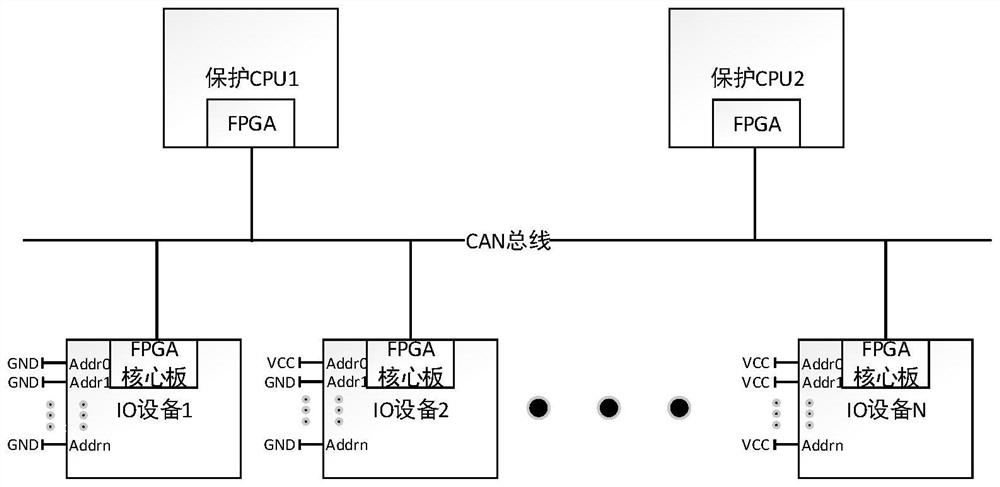
[0034] Please refer to figure 1 , a microcomputer protection device system architecture diagram, the protection CPU1 and the protection CPU2 are connected to the CAN bus through the FPGA, the IO device is connected to the CAN bus through the core board, and the CAN bus establishes a high-bandwidth communication channel between the protection CPU and the IO device. Uniform hardware encoding of the address bit Addr, so as to assign a unique address to each IO device, and the IO device identifies the Addr port to obtain its own address, so that each IO device has a unique legalized identity in the system.

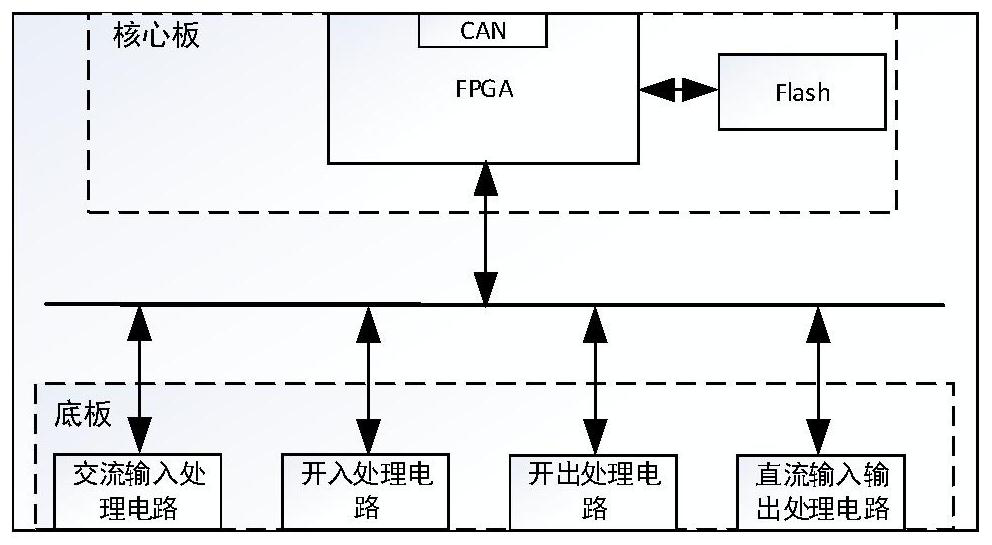
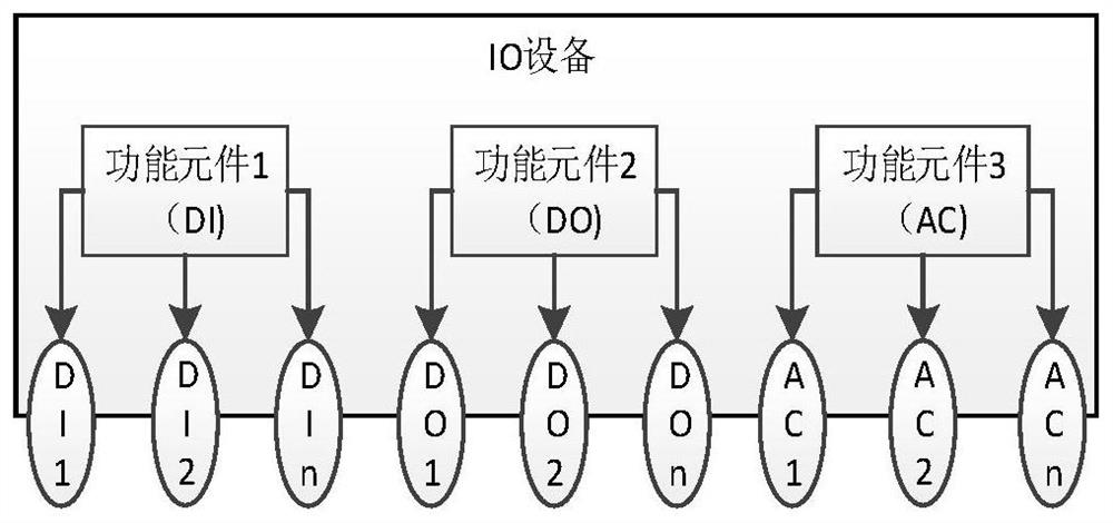
[0035] figure 2 A schematic diagram of the IO device architecture is given. The IO device adopts the design method of the core board and the expandable backplane. The core board is designed with FPGA and Flash storage unit. The FPGA is connected to the CAN bus to realize the communication between the IO device and the protection CPU. The Flash stores the IO Device configurat...


PUM


Abstract

The invention discloses IO equipment and a microcomputer protection device in the technical field of power system automation, and the IO equipment comprises a core board and an extensible bottom board, the core board is connected with the extensible bottom board through a data line, receives external data collected by circuits with different functions, and transmits the external data to the extensible bottom board through a data line; a control command is sent to the circuit execution units with different functions, and the extensible bottom plate is matched with the core plate to complete data input, output and isolation. Various changes can be achieved according to requirements, expandability is high, IO equipment with new characteristics can be added only by designing an expansion bottom plate, and the development scale can be reduced.

Description

technical field [0001] The invention relates to an IO device and a microcomputer protection device, belonging to the technical field of power system automation. Background technique [0002] Usually, the hardware circuit of microcomputer protection is composed of six functional units, namely microcomputer main system, working power supply, data acquisition system, switching input and output circuit, communication interface and man-machine dialogue system. Among them, the switch input and output and data acquisition system can be broadly defined as IO device systems. Different types of IO devices are usually designed by special circuits, and the placement position is bound to the slot on the backplane, so the position is not interchangeable. At the same time, Usually at the beginning of the design, it is necessary to design according to the maximum resource. As time goes by, the limitations of this design will gradually be exposed, and it will be difficult to expand in the la...

Claims


Application Information

Patent Timeline
Patent Type & Authority Applications(China)
IPC IPC(8): G06F13/362G06F13/38
CPCG06F13/362G06F13/385
Inventor 许学芳丁俊健胡恩俊罗铭
Owner NANJING GUODIAN NANZI WEIMEIDE AUTOMATION CO LTD
Learn More