Volute type discharge section structure for multi-stage pump and multi-stage pump

A multi-stage pump and volute type technology, which is applied to parts, pumps, and pump elements of pumping devices for elastic fluids, can solve the problems of shortened axial size, turbulent liquid flow, and many loss points, and achieve The effect of reducing friction loss, uniform pressure and uniform change

Pending Publication Date: 2022-03-01
SHANGHAI LIANCHENG(GRP) CO LTD
View PDF1 Cites 0 Cited by
  • Summary
  • Abstract
  • Description
  • Claims
  • Application Information

AI Technical Summary

Problems solved by technology

However, this structure has the following defects: 1. After the liquid flows out from the final stage impeller 2, it passes through the two hydraulic components of the final guide vane and the annular pressure water chamber respectively. In the final guide vane, the liquid first passes through the positive guide vane to diffuse , resulting in diffusion loss, and then when the final guide vane enters the annular pressurized water chamber, the two liquids are mixed with each other, resulting in impact loss, so the liquid flow is more chaotic, with many loss points and high energy consumption; 2. The structure has the final guide vane The vane and the inner flow channel are two parts of the discharge section of the annular pressurized water chamber. Not only the discharge section needs to be processed, but also the final guide vane needs to be processed, which is a waste of materials and manpower.
However, because the multi-stage pump needs to shorten the axial dimension as much as possible to ensure the reliable operation of the pump, after the ordinary spiral pressure water chamber is used, the liquid needs to spread to both sides after the impeller comes out. In order to ensure smooth water outlet and ensure the throat area , will inevitably increase the axial size of the pump, so there is no spiral discharge section structure in multi-stage pumps currently on the market

Method used


Image

  • Volute type discharge section structure for multi-stage pump and multi-stage pump
  • Volute type discharge section structure for multi-stage pump and multi-stage pump
  • Volute type discharge section structure for multi-stage pump and multi-stage pump

Examples


Embodiment Construction

[0030] The present invention will be described in detail below in conjunction with the accompanying drawings and specific embodiments. This embodiment is carried out on the premise of the technical solution of the present invention, and detailed implementation and specific operation process are given, but the protection scope of the present invention is not limited to the following embodiments.

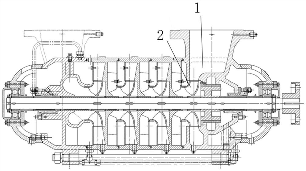
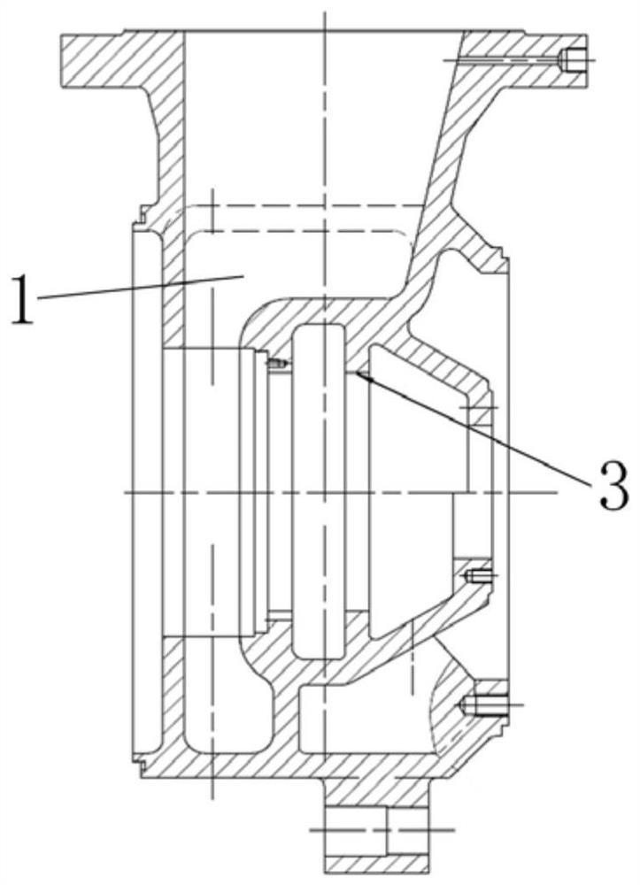
[0031] like figure 2 and image 3 As shown, this embodiment provides a volute discharge section structure for a multistage pump, which is installed in a certain type of multistage pump. The volute type discharge section structure includes a volute type discharge section cavity 1 . The final impeller 2 of the multistage pump is directly connected to the inlet of the cavity 1 of the discharge section, and the outlet of the cavity 1 of the discharge section is connected to the outlet of the multistage pump.

[0032] like Figure 4 and Figure 5 As shown, the specific structure of t...


PUM


Abstract

The invention relates to a volute type discharge section structure for a multi-stage pump and the multi-stage pump, the discharge section structure comprises a volute type discharge section cavity, a last-stage impeller of the multi-stage pump is directly connected with an inlet of the discharge section cavity, an outlet of the discharge section cavity is connected with an outlet of the multi-stage pump, and the section of the discharge section cavity is gradually enlarged from the inlet to the outlet. The inlet section, the middle section and the outlet section are connected in sequence. The section of the inlet section is a first rounded rectangle, and the length of the first rounded rectangle is sequentially changed from small to large; the section of the middle section is a combination of a first rounded rectangle and a second rounded rectangle, the second rounded rectangle and the second rounded rectangle form an L shape, and the length of the second rounded rectangle changes from small to large. Compared with the prior art, the structure mode that an existing last-stage guide vane and an annular pumping chamber are overlaid is replaced, under the condition that the axial size of the pump is not increased, friction loss is reduced, the efficient area of the pump is widened, the last-stage guide vane is omitted, and the manufacturing cost is reduced.

Description

technical field [0001] The invention relates to the field of multistage pumps, in particular to a volute type discharge section structure for the multistage pump and the multistage pump. Background technique [0002] The discharge section of the segmental multistage pump generally adopts the structure of the final guide vane and the annular pressurized water chamber, such as figure 1 shown in A and B. However, this structure has the following defects: 1. After the liquid flows out from the final stage impeller 2, it passes through the two hydraulic components of the final guide vane and the annular pressure water chamber respectively. In the final guide vane, the liquid first passes through the positive guide vane to diffuse , resulting in diffusion loss, and then when the final guide vane enters the annular pressurized water chamber, the two liquids are mixed with each other, resulting in impact loss, so the liquid flow is more chaotic, with many loss points and high energ...

Claims


Application Information

Patent Timeline
IPC IPC(8): F04D29/42F04D1/06
CPCF04D29/426F04D29/4293F04D1/06
Inventor 陆霞杰刘锋
Owner SHANGHAI LIANCHENG(GRP) CO LTD
Why Eureka
Try Eureka