Silica sand side unloading device

A material receiving device and unloading device technology, which is applied in the directions of loading/unloading, transportation and packaging, conveyor objects, etc., can solve the problems of reducing the conveying efficiency, the conveyor belt needs to be cleaned, and the efficiency of unloading is affected.

Active Publication Date: 2022-04-08
山东莱州福利泡花碱有限公司
View PDF11 Cites 0 Cited by
  • Summary
  • Abstract
  • Description
  • Claims
  • Application Information

AI Technical Summary

Problems solved by technology

[0005] But this method has the following problems. The unloading method of this invention is to unload by tilting the connecting plate, that is, to completely rely on the gravity of the natural fall of the silica sand. There is friction between the connecting plates, and the falling speed of the silica sand during unloading is not ideal, which affects the efficiency of unloading. At the same time, part of the silica sand will adhere to the surface of the connecting plates during the unloading process, and there is a need for docking The problem of material plate cleaning also affects the efficiency of silica sand unloading. Even if it is unloaded with the conveyor belt, the position of the silica sand on the conveyor belt will not change during the rotation of the conveyor belt, that is, the silica sand will be transferred from falling to conveying. The belt is stationary relative to the conveyor belt for a period of time until it is separated from the conveyor belt. During this period of time, the silica sand will adhere to the conveyor belt due to its viscosity, which not only reduces the conveying efficiency, but also leads to failure after the work is completed. Conveyor belt needs to be cleaned

Method used


Image

  • Silica sand side unloading device
  • Silica sand side unloading device
  • Silica sand side unloading device

Examples


Embodiment Construction

[0029] In order to make the purpose, technical solution and advantages of the present invention clearer, the technical solution of the present invention will be clearly and completely described below in conjunction with specific embodiments of the present invention and corresponding drawings. Apparently, the described embodiments are only some of the embodiments of the present invention, but not all of them. Based on the embodiments of the present invention, all other embodiments obtained by persons of ordinary skill in the art without making creative efforts belong to the protection scope of the present invention.

[0030] The technical solutions provided by various embodiments of the present invention will be described in detail below in conjunction with the accompanying drawings.

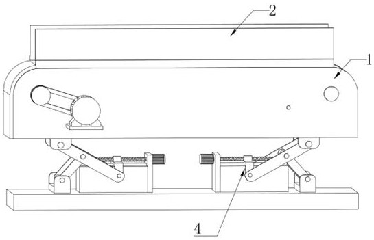
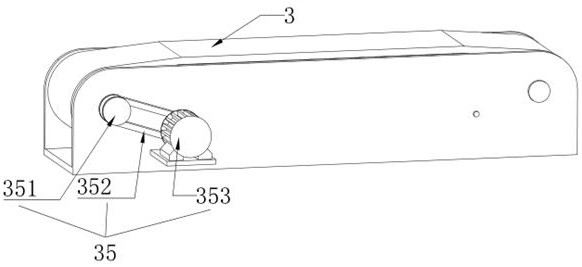
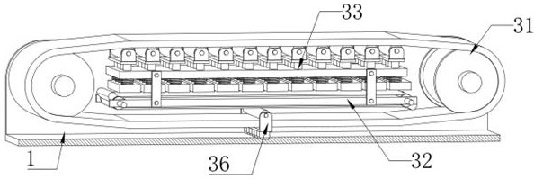
[0031] Such as Figure 1-Figure 8 As shown, the embodiment of the present invention provides a silica sand side unloading device, including a mounting frame 1 and a side baffle 2, and also inclu...


PUM

PropertyMeasurementUnit
particle diameteraaaaaaaaaa

Abstract

The invention discloses a silica sand side unloading and connecting device, which belongs to the technical field of auxiliary unloading equipment, and includes a mounting frame and a side baffle, and also includes a quick unloading device and an inclined docking device. The inclined docking device is horizontally arranged, and the installation The frame is arranged on the top of the inclined docking device, and there are two side baffles, and the two side baffles are arranged symmetrically on both sides of the top of the installation frame, and the quick unloading device is arranged on the installation frame. The unloading device includes a conveying assembly, a circular driving assembly and a material ejecting assembly, the conveying assembly is arranged in the mounting frame, the circulating driving assembly is arranged inside the conveying assembly, and the ejecting assembly is arranged on the circulating driving assembly; the device While avoiding the silica sand falling into the area outside the silica sand silo during the unloading process, the unloading speed is improved, and there is no need to clean the material receiving platform or the surface of the device, thereby greatly improving the efficiency of the silica sand unloading.

Description

technical field [0001] The invention relates to the technical field of auxiliary unloading equipment, in particular to a silica sand side unloading and receiving device. Background technique [0002] Silica sand, also known as silicon dioxide or quartz sand. Refractory particles with quartz as the main mineral component and a particle size of 0.020mm-3.350mm can be divided into artificial silica sand, washed sand, scrubbed sand, selected (flotation) sand and other natural silica sand according to different mining and processing methods. Silica sand is a hard, wear-resistant, chemically stable silicate mineral. [0003] When the extended truck transports the silica sand to the silica sand silo for unloading, due to the lack of special receiving equipment, the truck is usually driven close to the edge of the silica sand silo, and the carriage containing the silica sand is controlled to tilt towards the silo for unloading , although this unloading method is feasible, in order...

Claims


Application Information

Patent Timeline
Patent Type & Authority Patents(China)
IPC IPC(8): B65G67/24B65G65/32B65G41/00B65G23/22B65G23/04B65G47/22B65G15/60B65G23/44
CPCB65G67/24B65G65/32B65G41/005B65G23/22B65G23/04B65G47/22B65G15/60B65G23/44
Inventor 于浩然
Owner 山东莱州福利泡花碱有限公司
Why Eureka
Try Eureka