
Aluminum template numerical control slot milling machine

A CNC milling machine and aluminum formwork technology, which is applied in the direction of milling machine equipment, milling machine equipment details, metal processing machinery parts, etc., can solve the problems of insufficient feeding, setbacks, and steps in aluminum formwork milling grooves, etc., so as to facilitate long-term use , save energy and reduce damage

Inactive Publication Date: 2022-02-25
山西建投建筑产业有限公司 +2
View PDF14 Cites 0 Cited by
  • Summary
  • Abstract
  • Description
  • Claims
  • Application Information

AI Technical Summary

Problems solved by technology

[0005] The purpose of the present invention is to overcome the above-mentioned problems existing in the prior art, to provide an aluminum formwork numerical control groove milling machine, to solve the problem of the split design of the equipment cutter head structure and the pressing mechanism, to make the milling groove more stable, and to solve the problem of When the feed mechanism moves, the feed is not in place and the situation is prone to setbacks, resulting in problems such as steps when the aluminum formwork is milling grooves, and the finish cannot meet the technical requirements.

Method used


Image

  • Aluminum template numerical control slot milling machine
  • Aluminum template numerical control slot milling machine
  • Aluminum template numerical control slot milling machine

Examples


Embodiment Construction

[0059] The following is attached Figure 1-25 The present invention is described in further detail.

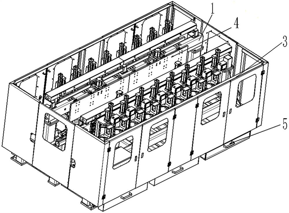
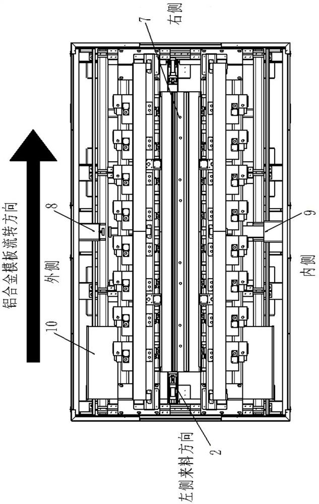
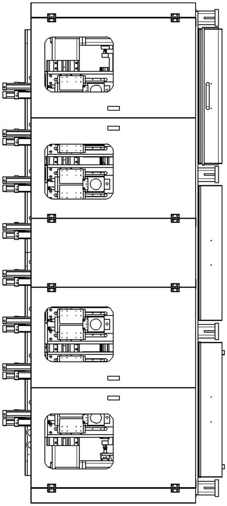
[0060] An embodiment provided by the present invention: as figure 1 with figure 2 As shown, the aluminum template CNC slotting machine has a PLC control system of the prior art, including a protective cover frame 3, and the inner cavity of the protective cover frame 3 is symmetrically provided with feed mechanisms 1 on both sides, and one group is the outer side Traversing feeding mechanism 8, the other group is inner traversing feeding mechanism 9, and the left end of the side where the outer traversing feeding mechanism 8 and the inner traversing feeding mechanism 9 are far away from each other is provided with a power distribution cabinet 10. The electric cabinet 10 is installed in the protective cover frame 3, and the upper end of the side where the two groups of feeding mechanisms 1 are close to each other is provided with a pressing mechanism 4, such as figure 1 , ...


PUM


Abstract

The invention discloses an aluminum template numerical control slot milling machine, and relates to the field of modern equipment manufacturing. The aluminum template numerical control slot milling machine comprises a protective cover frame; feeding mechanisms are symmetrically arranged on the front side and the rear side of an inner cavity of the protective cover frame, wherein one is an outer side transverse moving feeding mechanism, and the other is an inner side transverse moving feeding mechanism; pressing mechanisms are arranged at the upper ends of the sides, close to each other, of the two feeding mechanisms, and aluminum scrap collecting devices are arranged on the front side and the rear side of the bottom of the protective cover frame correspondingly; the left ends of the sides, away from each other, of the outer side transverse moving feeding mechanism and the inner side transverse moving feeding mechanism are each provided with a power distribution cabinet; a clamping unit is arranged between the two sets of feeding mechanisms, and groove milling mechanisms are arranged on the sides, away from each other, of the two sets of feeding mechanisms. The problem of split type design of a tool bit structure and a pressing mechanism of the equipment is solved, so that the groove milling is more stable, and the problems that the conditions that feeding is not in place and pause easily occur when the feeding mechanism moves, so that steps exist when the aluminum template is subjected to groove milling, and the smoothness cannot meet the technical requirements are solved.

Description

technical field [0001] The invention relates to the field of modern equipment manufacturing, in particular to an aluminum formwork numerical control groove milling machine. Background technique [0002] The base of the traditional equipment is to move back and forth after the cylinder compresses the aluminum profile, and the slot milling cutter head does not move. Now the pressing mechanism of the construction aluminum slot milling machine on the market adopts the method of hanging plates on both sides and moving the knife in the middle. During the process, a part of time was wasted from the front hanging board to the rear hanging board, resulting in slow processing speed and low productivity. [0003] The traditional feed mechanism uses a motor-accelerated reducer mode, and the gears of the reducer have a large fit clearance, which is prone to feed inadequacy and setbacks when the feed mechanism moves, resulting in steps when the aluminum formwork is milling grooves, and th...

Claims


Application Information

Patent Timeline
Patent Type & Authority Applications(China)
IPC IPC(8): B23C3/28B23Q11/10B23Q11/00B23Q11/08B23Q5/26B23Q7/00B23Q3/08
CPCB23C3/28B23Q11/10B23Q11/005B23Q11/0067B23Q5/26B23Q11/08B23Q3/08B23Q7/00B23Q2703/04
Inventor 侯军强赵志红牛小平赵宇飞田海兵李鑫王志强张正高锐
Owner 山西建投建筑产业有限公司
Learn More