
Delay locked loop circuit

A delay-locked loop and circuit technology, which is applied in the direction of electrical components, automatic power control, etc., can solve problems such as phase mismatch

Pending Publication Date: 2022-02-22
CHANGXIN MEMORY TECH INC
View PDF0 Cites 2 Cited by
  • Summary
  • Abstract
  • Description
  • Claims
  • Application Information

AI Technical Summary

Problems solved by technology

[0004] Based on this, it is necessary to provide a delay locked loop circuit for the phase mismatch problem between the clock signal and the drifting DQS signal

Method used


Image

  • Delay locked loop circuit
  • Delay locked loop circuit
  • Delay locked loop circuit

Examples


Embodiment Construction

[0047] In order to facilitate the understanding of the present invention, the present invention will be described more fully below with reference to the associated drawings. A preferred embodiment of the invention is shown in the drawings. However, the present invention can be embodied in many different forms and is not limited to the embodiments described herein. Rather, these embodiments are provided so that the disclosure of the present invention will be thorough and complete.

[0048] Unless otherwise defined, all technical and scientific terms used herein have the same meaning as commonly understood by one of ordinary skill in the technical field of the invention. The terms used herein in the description of the present invention are for the purpose of describing specific embodiments only, and are not intended to limit the present invention. As used herein, the term "and / or" includes any and all combinations of one or more of the associated listed items.

[0049] In the...


PUM


Abstract

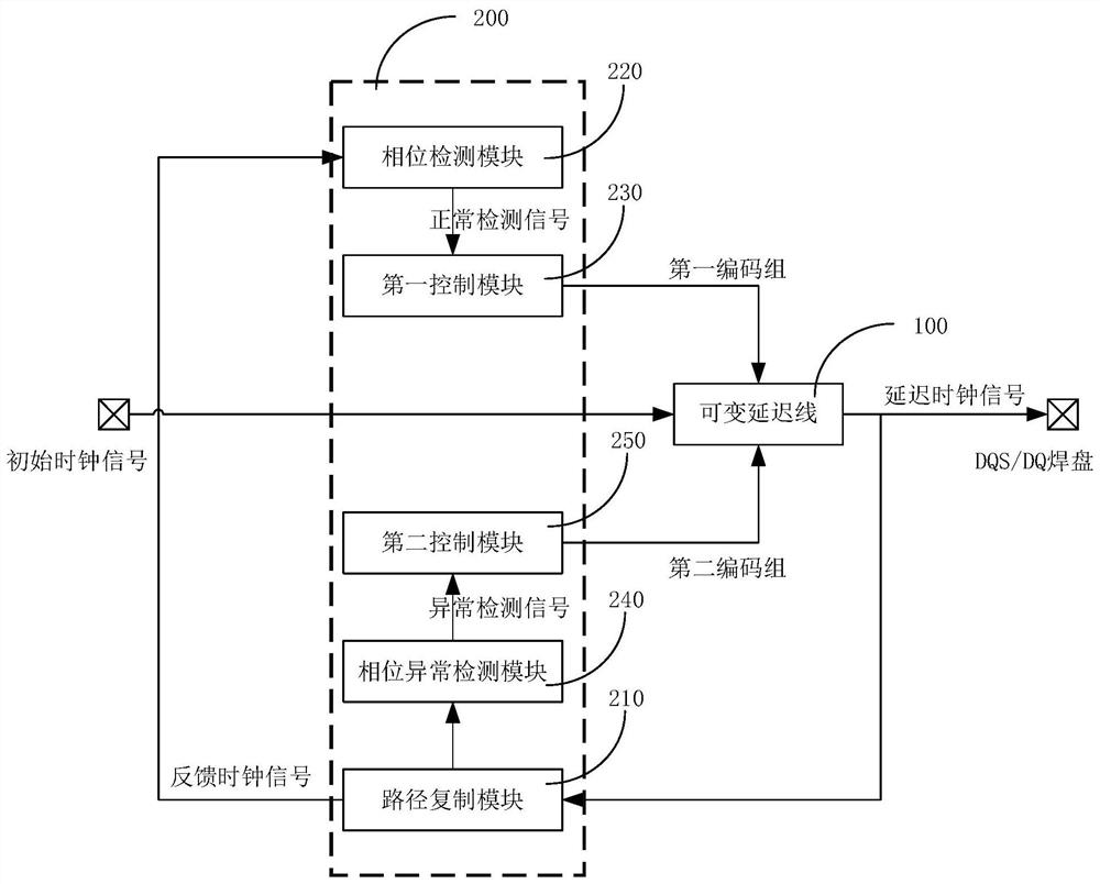
The present invention relates to a delay locked loop circuit. The delay locked loop circuit comprises a variable delay line used for delaying an initial clock signal to generate a delayed clock signal; and a control circuit connected with the variable delay line and used for controlling the variable delay line to carry out delay adjustment in a first mode and carrying out delay adjustment in a second mode on the variable delay line when the delayed clock signal meets preset conditions, wherein a stepping value of each time of the delay adjustment in the first mode is a first stepping value, a stepping value of each time of the delay adjustment in the second mode is a second stepping value, and the second stepping value is larger than the first stepping value. According to the invention, by judging whether the delayed clock signal meets the preset conditions or not, an actual state of the delayed clock signal can be obtained to adjust delay of the variable delay line according to different strategies, so that output of the delay locked loop circuit can dynamically and adaptively track time sequence changes of the delayed clock signal, and a matching degree between the initial clock signal (CK) and a drifting DQS signal is improved.

Description

technical field [0001] The invention relates to the technical field of semiconductor integrated circuits, in particular to a delay locked loop circuit. Background technique [0002] With the continuous development of science and technology, double data rate (Double Data Rate, DDR) dynamic random access memory (Dynamic Random Access Memory, DRAM) is widely used in various electronic devices, such as computers, mobile phones, tablet computers, etc. . When the DRAM performs data read and write operations, it is necessary to rely on the DQS signal to realize signal synchronization between the memory and the controller. Specifically, if the data is read from the memory, the controller judges when to receive the read data according to the DQS signal sent by the memory. [0003] In order to realize the accurate reading of data, it is necessary to align the clock signal of the controller with the DQS signal on the rising edge to ensure that the data is correct. However, during th...

Claims


Application Information

Patent Timeline
IPC IPC(8): H03L7/081
CPCH03L7/0818H03L7/081
Inventor 陈晓飞郑载勲李勳严允柱
Owner CHANGXIN MEMORY TECH INC
Learn More