
Event camera, depth event point diagram acquisition method and device, equipment and medium

An acquisition method and event point technology, applied in the field of computer vision, can solve the problems of affecting the response speed, complex operation logic, and time-consuming, etc., and achieve the effect of fast response speed and simple operation logic

Inactive Publication Date: 2022-02-18
JIHUA LAB
View PDF9 Cites 4 Cited by
  • Summary
  • Abstract
  • Description
  • Claims
  • Application Information

AI Technical Summary

Problems solved by technology

[0003] However, the current event camera only has monocular output, and binocular construction is required when acquiring depth information. The binocular event camera needs to jointly calibrate and divide the event information obtained by binoculars separately to calculate and obtain depth information, and its operation logic is complex. It takes a lot of time, especially some loop and redundancy detection algorithms included in it will cause further delay and affect the response speed
[0004] For the above problems, there is no effective technical solution

Method used


Image

  • Event camera, depth event point diagram acquisition method and device, equipment and medium
  • Event camera, depth event point diagram acquisition method and device, equipment and medium
  • Event camera, depth event point diagram acquisition method and device, equipment and medium

Examples


Embodiment Construction

[0047]The following will clearly and completely describe the technical solutions in the embodiments of the present application with reference to the accompanying drawings in the embodiments of the present application. Obviously, the described embodiments are only some of the embodiments of the present application, not all of them. The components of the embodiments of the application generally described and illustrated in the figures herein may be arranged and designed in a variety of different configurations. Accordingly, the following detailed description of the embodiments of the application provided in the accompanying drawings is not intended to limit the scope of the claimed application, but merely represents selected embodiments of the application. Based on the embodiments of the present application, all other embodiments obtained by those skilled in the art without making creative efforts belong to the scope of protection of the present application.

[0048] It should b...


PUM


Abstract

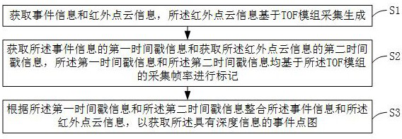
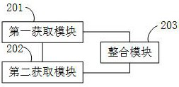
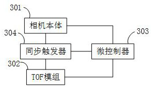
The invention relates to the technical field of computer vision, and particularly discloses an event camera, a depth event point diagram acquisition method and device, equipment and a medium, the acquisition method comprises the following steps: acquiring event information and infrared point cloud information, the infrared point cloud information being acquired and generated based on a TOF module; obtaining first timestamp information of the event information and second timestamp information of the infrared point cloud information, wherein the first timestamp information and the second timestamp information are marked based on the collection frame rate of the TOF module; integrating the event information and the infrared point cloud information according to the first timestamp information and the second timestamp information to obtain the event point diagram with the depth information; the acquisition method has the advantages of being simple in operation logic and high in response speed.

Description

technical field [0001] The present application relates to the technical field of computer vision, in particular, to an event camera, a method, a device, a device and a medium for acquiring a depth event point map. Background technique [0002] Due to the limitation of frame rate and light intensity when sampling, traditional cameras have great difficulties in identifying high-speed moving objects or moving objects in dark light environments. Event cameras can solve these problems well, mainly through Set the illumination threshold and detect the light intensity changes at each point to passively trigger the output of event information, and then accelerate the output of event information through FPGA, so as to obtain the displacement information of approximately continuous high-speed moving objects in dark or strong light environments. [0003] However, the current event camera only has monocular output, and binocular construction is required when acquiring depth information....

Claims


Application Information

Patent Timeline
IPC IPC(8): H04N13/204H04N5/33
CPCH04N13/204H04N5/33
Inventor 何昊名霍震古家威陈海龙邓涛李志建蔡维嘉王济宇黄秀韦董志岩
Owner JIHUA LAB
Learn More