Eureka AIR delivers breakthrough ideas for toughest innovation challenges, trusted by R&D personnel around the world.

Plasma processing apparatus and plasma processing method

A plasma and processing device technology, applied in the field of plasma processing devices

Pending Publication Date: 2022-02-18
TOKYO ELECTRON LTD
View PDF1 Cites 0 Cited by
  • Summary
  • Abstract
  • Description
  • Claims
  • Application Information

AI Technical Summary

Problems solved by technology

The substrate holder has bias electrodes

Method used


Image

  • Plasma processing apparatus and plasma processing method
  • Plasma processing apparatus and plasma processing method
  • Plasma processing apparatus and plasma processing method

Examples


Embodiment Construction

[0015] Various exemplary embodiments are described below.

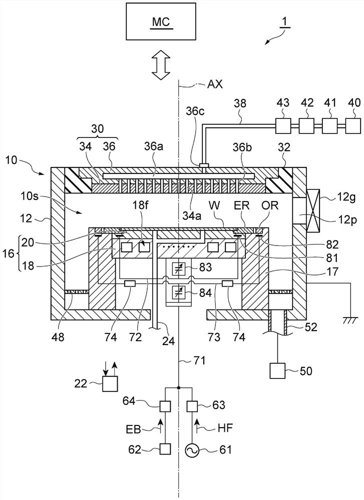
[0016] In an exemplary embodiment, a plasma processing apparatus is provided. A plasma processing apparatus includes a chamber, a substrate holder, a high-frequency power supply, and a bias power supply. The substrate holder has bias electrodes. The high-frequency power supply is configured to generate high-frequency power to be supplied to the high-frequency electrode in order to generate plasma above the substrate supported by the substrate holder in the chamber. The bias power supply is connected to the bias electrode via an electrical path. The edge ring is mounted on the substrate holder. The edge ring is electrically connected to a bias power supply, or to another bias power supply, via an impedance adjuster providing a variable impedance between the bias electrode and the edge ring or between the electrical path and the edge ring. The outer ring extends radially and on the outside with respect to the edge r...


PUM


Abstract

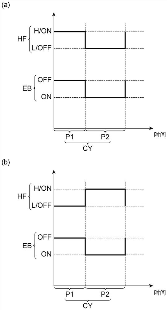
A plasma processing apparatus includes a chamber, a substrate support, a high-frequency power source, and a bias power source. The high-frequency power supply supplies high-frequency power to the high-frequency electrode. The bias power supply applies an electrical bias to the bias electrode. An edge ring mounted on the substrate support receives a portion of the electrical bias or another electrical bias. The outer ring extends radially and outwardly with respect to the edge ring, and receives a portion of the high-frequency power. The power level of the high-frequency power is changed in synchronization with the electrical bias in each cycle of the electrical bias.

Description

technical field [0001] Exemplary embodiments of the present invention relate to a plasma processing apparatus and a plasma processing method. Background technique [0002] The plasma processing apparatus is used for plasma processing of a substrate. The plasma processing apparatus includes a chamber, an electrostatic chuck, and a lower electrode. The electrostatic chuck and the lower electrode are arranged in the chamber. The electrostatic chuck is arranged on the lower electrode. The electrostatic chuck supports the edge ring placed thereon. The fringe ring is sometimes called the focus ring. The electrostatic chuck supports the substrate arranged in the area surrounded by the edge ring. When plasma processing is performed in the plasma processing apparatus, gas is supplied into the chamber. And, high-frequency power is supplied to the lower electrode. A plasma is formed from the gas in the chamber. Substrates are treated with chemical species such as ions and radic...

Claims


Application Information

Patent Timeline
IPC IPC(8): H01J37/32
CPCH01J37/32706H01J37/32082H01J37/32091H01J37/32642H01J37/32183H01J37/32146H01J37/32568H01J37/32697H01J37/32715H01J37/32174H01J37/32532H01L21/6831H01J2237/2007
Inventor 舆水地盐
Owner TOKYO ELECTRON LTD
Why Eureka
Eureka Blog
Learn More