
Two-way pressure high-temperature butterfly valve

A high-temperature butterfly valve and valve body technology, which is applied in the direction of lifting valve, valve details, valve device, etc., can solve the problems of butterfly valve sealing performance degradation, reduced service life of butterfly plate, damage to butterfly plate, etc., to ensure normal use and improve use Longevity and the effect of enhancing the overall airtightness

Pending Publication Date: 2022-02-18
闫皓男
View PDF1 Cites 1 Cited by
  • Summary
  • Abstract
  • Description
  • Claims
  • Application Information

AI Technical Summary

Problems solved by technology

[0003] Butterfly valve has the advantages of simple structure, small size, light weight, low material consumption, small installation size, small driving torque, easy and fast operation, etc. It is one of the fastest-growing valve varieties in the past ten years. Butterfly valves are widely used. , and the variety and quantity used are still expanding. Existing butterfly valves generally adopt a metal-to-metal sealing triple-eccentric structure, and its disadvantage is that when the operating conditions require a two-way sealing function, the butterfly valve with a triple-eccentric structure Only one-way good sealing can be guaranteed, resulting in a decline in the overall sealing performance of the butterfly valve
[0005] The above-mentioned patent uses the combination of the booster device and the medium flow direction control mechanism to add an additional force to the butterfly plate and increase the sealing specific pressure between the sealing surface of the butterfly plate and the sealing surface of the valve seat, thereby improving the overall sealing performance of the butterfly valve. However, due to the large contact area between the butterfly plate and the fluid during the use of the existing butterfly valve, when the butterfly plate is closed, it needs to bear the large pressure caused by the fluid. Over time, it is easy to cause deformation of the butterfly plate, thus affecting the butterfly plate. In addition, when the butterfly plate is adjusted to rotate, the butterfly plate will be affected by the resistance of the fluid, which will cause damage to the butterfly plate, reduce the service life of the butterfly plate, and affect the normal use of the butterfly valve.

Method used


Image

  • Two-way pressure high-temperature butterfly valve
  • Two-way pressure high-temperature butterfly valve
  • Two-way pressure high-temperature butterfly valve

Examples


Embodiment Construction

[0031] The following will be combined with the present invention to realize some embodiments of the present invention, rather than all embodiments. Based on the embodiments of the present invention, all other embodiments obtained by persons of ordinary skill in the art without making creative efforts belong to the protection scope of the present invention.

[0032] In describing the present invention, it is to be understood that the terms "center", "longitudinal", "transverse", "length", "width", "thickness", "upper", "lower", "front", " Back", "Left", "Right", "Vertical", "Horizontal", "Top", "Bottom", "Inner", "Outer", "Clockwise", "Counterclockwise", etc. or The positional relationship is based on the orientation or positional relationship shown in the drawings, which are only for the convenience of describing the present invention and simplifying the description, rather than indicating or implying that the referred device or element must have a specific orientation, be const...


PUM


Abstract

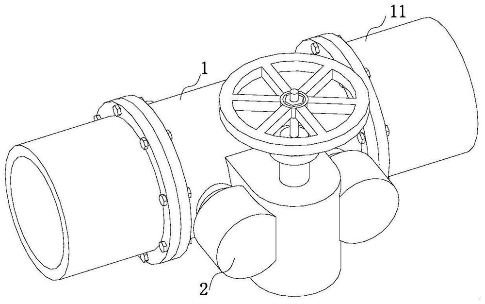
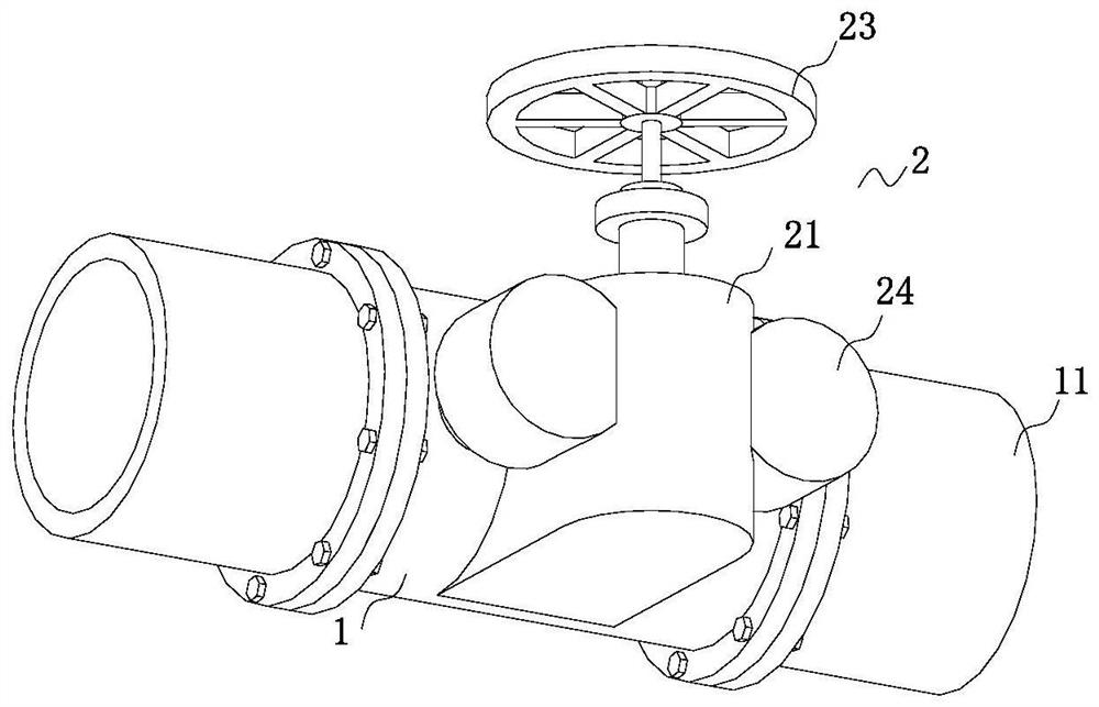
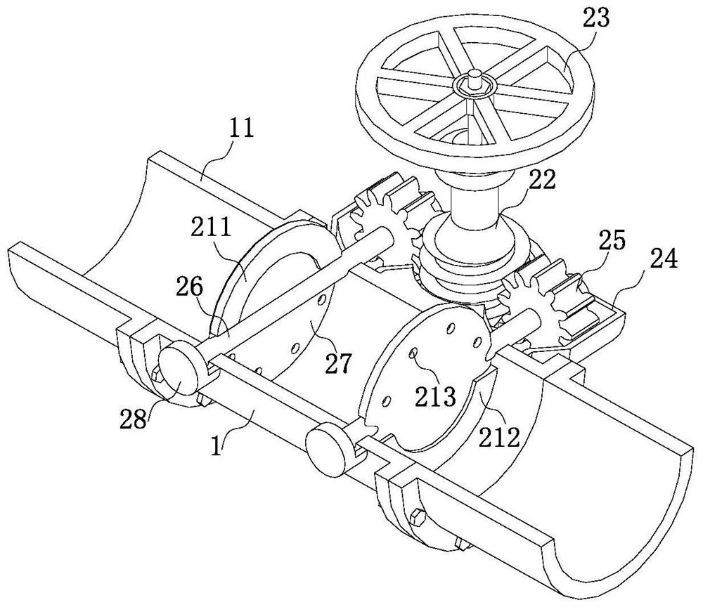
The invention relates to the technical field of valves, in particular to a two-way pressure high-temperature butterfly valve. The two-way pressure high-temperature butterfly valve comprises a valve body, wherein pipelines are fixedly connected to outer surfaces of the left side and the right side of the valve body through flange plates; an adjusting mechanism is fixedly connected to the center of the front end of an annular outer surface of the valve body; the adjusting mechanism comprises a connecting cylinder, a worm, a hand wheel, a driving chamber, a turbine, a connecting rod, butterfly plates and a cover plate; and the connecting cylinder is fixedly connected to the center of the front end of the annular outer surface of the valve body. According to the invention, the adjusting mechanism is arranged, and the two butterfly plates are attached to the valve body, so that the double-sealing effect is achieved, the two-way pressure high-temperature butterfly valve is suitable for working conditions that a butterfly valve is required to have a two-way sealing function, and the purpose of enhancing overall sealing performance of the butterfly valve is achieved; and a first semi-ring and a second semi-ring are arranged, and the first semi-ring and the second semi-ring are used for limiting and supporting the butterfly plates, so that the situation that when the butterfly plates are closed, the butterfly plates need to bear large pressure caused by fluid on the butterfly plates, and the butterfly plates are prone to deformation after long time is avoided.

Description

technical field [0001] The invention relates to the technical field of valves, in particular to a two-way pressure high temperature butterfly valve. Background technique [0002] Butterfly valve, also known as flap valve, is a regulating valve with simple structure, which can be used for switch control of low-pressure pipeline medium. A kind of valve, the valve can be used to control the flow of various types of fluids such as air, water, steam, various corrosive media, mud, oil, liquid metal and radioactive media, and it mainly plays the role of cutting and throttling on the pipeline; [0003] Butterfly valve has the advantages of simple structure, small size, light weight, low material consumption, small installation size, small driving torque, easy and fast operation, etc. It is one of the fastest-growing valve varieties in the past ten years. Butterfly valves are widely used. , and the variety and quantity used are still expanding. Existing butterfly valves generally ad...

Claims


Application Information

Patent Timeline
Patent Type & Authority Applications(China)
IPC IPC(8): F16K1/226F16K1/32F16K1/36F16K31/53F16K27/02
CPCF16K1/2261F16K1/32F16K1/36F16K31/53F16K27/0218
Inventor 闫皓男夏俊豪
Owner 闫皓男
Learn More