Gravel pile foundation stilling pool on deep covering layer and construction method

A technology of deep covering layer and construction method, applied in water conservancy engineering, marine engineering, coastline protection and other directions, can solve the problems of self-heavy structure of stilling pool, large foundation bearing capacity requirements, and endangering structural safety, etc., to avoid engineering volume. And the effect of increasing investment, saving engineering volume and engineering investment, and ensuring stability and safety

Pending Publication Date: 2022-02-18
CHINA POWER CONSRTUCTION GRP GUIYANG SURVEY & DESIGN INST CO LTD
View PDF6 Cites 0 Cited by
  • Summary
  • Abstract
  • Description
  • Claims
  • Application Information

AI Technical Summary

Problems solved by technology

[0004] There are also some projects where the bottom plate of the stilling tank is placed on the covering layer, and the foundation anchor bar is not arranged on the bottom plate of the stilling tank. Because the drainage channel is easily blocked by the sediment at the bottom of the stilling tank, no basic drainage channel is set up, and generally only rely on the self-weight of the bottom plate. To counteract the effect of uplift pressure, in order to make the stilling basin meet the anti-floating stability, the thickness of the bottom plate of the stilling basin on the deep covering layer is generally large, resulting in high engineering quantity and investment. The force requirements are relatively large, and the structure of the stilling pool is prone to subsidence and deformation due to insufficient bearing capacity of the bottom covering layer, which endangers the safety of the structure

Method used


Image

  • Gravel pile foundation stilling pool on deep covering layer and construction method
  • Gravel pile foundation stilling pool on deep covering layer and construction method

Examples


Embodiment 1

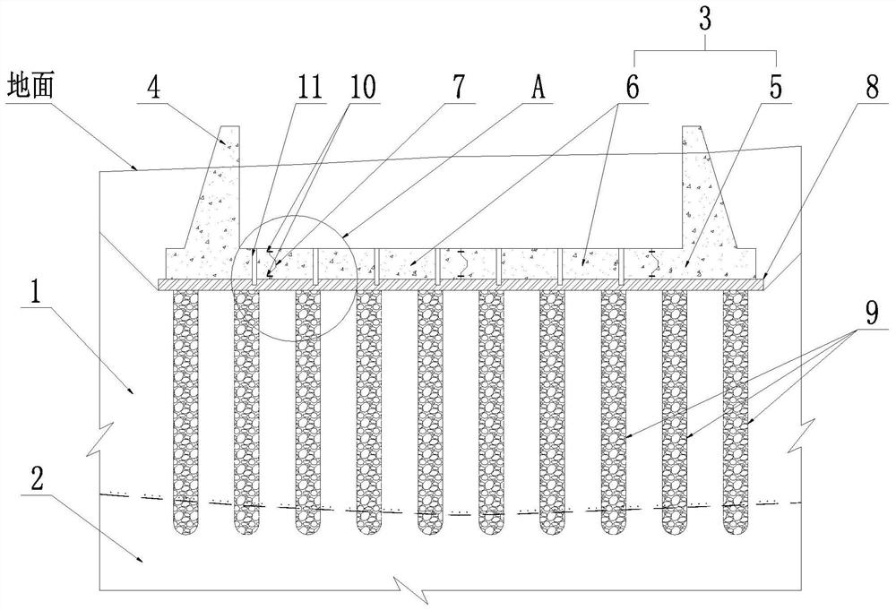
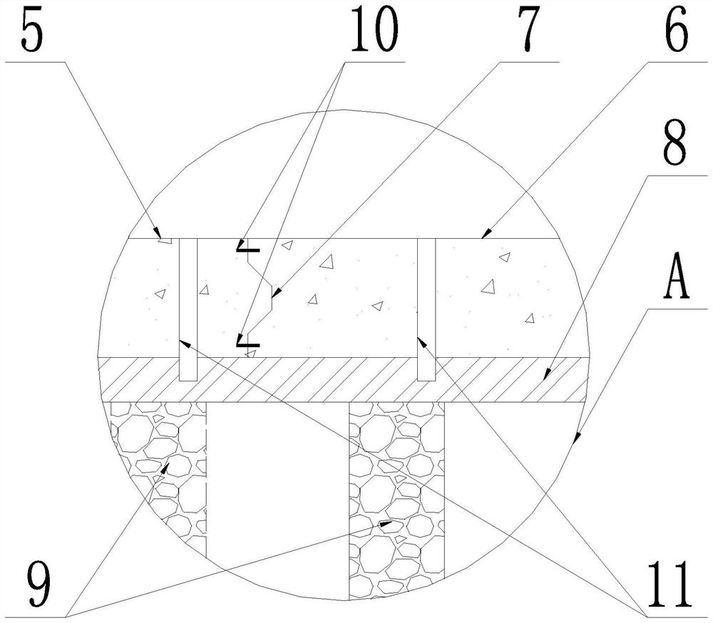
[0033] Embodiment 1 of the present invention: a gravel pile foundation stilling pool on a deep covering layer, including a covering layer 1, a bedrock layer 2, a bottom plate 3 and a side wall 4, and the bottom plate 3 includes two side bottom plates 5 and A plurality of middle bottom plates 6, a plurality of middle bottom plates 6 are placed between two side bottom plates 5, the bottom of the side wall 4 is connected to the upper surface of the side bottom plates 3, and a transverse There is also a transverse joint 7 between two adjacent middle bottom plates 6, a concrete cushion 8 is provided on the lower surface of the bottom plate 3, and a gravel pile 9 is arranged on the lower surface of the concrete cushion 8, and the gravel pile 9 runs through Covering layer 1, the pile bottom of gravel pile 9 is submerged into bedrock layer 2, and cover layer 1 is positioned at the top of bedrock layer 2.

Embodiment 2

[0034]Embodiment 2 of the present invention: a gravel pile foundation stilling pool on a deep covering layer, including a covering layer 1, a bedrock layer 2, a bottom plate 3 and a side wall 4, and the bottom plate 3 includes two side bottom plates 5 and A plurality of middle bottom plates 6, a plurality of middle bottom plates 6 are placed between two side bottom plates 5, the bottom of the side wall 4 is connected to the upper surface of the side bottom plates 3, and a transverse There is also a transverse joint 7 between two adjacent middle bottom plates 6, a concrete cushion 8 is provided on the lower surface of the bottom plate 3, and a gravel pile 9 is arranged on the lower surface of the concrete cushion 8, and the gravel pile 9 runs through Covering layer 1, the pile bottom of gravel pile 9 submerges into the bedrock layer 2, and the covering layer 1 is located on the upper part of the bedrock layer 2; the transverse joint 7 is provided with a water stop 10.

Embodiment 3

[0035] Embodiment 3 of the present invention: a gravel pile foundation stilling pool on a deep covering layer, including a covering layer 1, a bedrock layer 2, a bottom plate 3 and a side wall 4, and the bottom plate 3 includes two side bottom plates 5 and A plurality of middle bottom plates 6, a plurality of middle bottom plates 6 are placed between two side bottom plates 5, the bottom of the side wall 4 is connected to the upper surface of the side bottom plates 3, and a transverse There is also a transverse joint 7 between two adjacent middle bottom plates 6, a concrete cushion 8 is provided on the lower surface of the bottom plate 3, and a gravel pile 9 is arranged on the lower surface of the concrete cushion 8, and the gravel pile 9 runs through Covering layer 1, the pile bottom of gravel pile 9 is submerged into the bedrock layer 2, and the covering layer 1 is located on the upper part of the bedrock layer 2; the transverse joint 7 is provided with a water stop 10; the tr...


PUM


Abstract

The invention discloses a gravel pile foundation stilling pool on a deep covering layer. The gravel pile foundation stilling pool comprises the covering layer, a bedrock layer, a bottom plate and a side wall, the bottom plate comprises two side bottom plates and a plurality of middle bottom plates, the middle bottom plates are arranged between the two side bottom plates, the bottom of the side wall is connected with the upper surfaces of the side bottom plates, transverse joints are arranged between the middle-section bottom plates and the side bottom plates, transverse joints are also arranged between every two adjacent middle-section bottom plates, a concrete cushion layer is arranged on the lower surface of each bottom plate, vertical drainage channels are formed in the bottom plates and are embedded into the concrete cushion layers, gravel piles are arranged on the lower surfaces of the concrete cushion layers and penetrate through the covering layer, and the pile bottoms of the gravel piles are embedded into the bedrock layer, meanwhile, the invention further discloses a construction method of the gravel pile foundation stilling pool on the deep covering layer. On the premise of reducing excavation of the covering layer foundation of the stilling pool and the engineering amount of structural concrete, the bearing capacity of the covering layer foundation is improved, the structural stability and safety of the stilling pool can be guaranteed, and the engineering amount and the engineering investment are saved.

Description

technical field [0001] The invention relates to a gravel pile foundation stilling pool on a deep covering layer and a construction method thereof, belonging to the technical field of water conservancy and hydropower engineering. Background technique [0002] In water conservancy and hydropower engineering, for the high-speed discharge flow, in order to reduce the erosion of the natural channel behind the dam and ensure the safety of the main body of the dam, three energy dissipation methods are mainly used to dissipate the energy of the discharge flow: deflecting flow energy dissipation, bottom flow dissipation energy, surface flow energy dissipation. When the topographical conditions of the discharge water flow energy dissipation area are limited, the erosion resistance of the river bank is poor, the downstream water level is relatively shallow, and the water level varies greatly, the energy dissipation method of the discharge water flow is usually the bottom flow energy di...

Claims


Application Information

Patent Timeline
Patent Type & Authority Applications(China)
IPC IPC(8): E02B8/06E02B8/00
CPCE02B8/06E02B8/00
Inventor 王瑞
Owner CHINA POWER CONSRTUCTION GRP GUIYANG SURVEY & DESIGN INST CO LTD
Why Eureka
Try Eureka