Electroacoustic transducer with multiple impact protection

An electro-acoustic transducer, impact protection technology, applied in the direction of transducer shell/cabinet/support, spring/shock absorber, mechanical equipment, etc. The problem of buffering the large moving stroke, etc., can improve the impact protection, the effect of improving the impact protection, and the effect of slowing down the impact stroke.

Pending Publication Date: 2022-02-15
GAOYOU HUASHENG ELECTRONICS
View PDF0 Cites 0 Cited by
  • Summary
  • Abstract
  • Description
  • Claims
  • Application Information

AI Technical Summary

Problems solved by technology

[0002] An electroacoustic transducer is a device used to receive an electrical signal and convert the electrical signal into an acoustic signal, or receive an acoustic signal and convert the acoustic signal into an electrical signal. When the electroacoustic transducer is dropped or bumped When impacting, the internal transducer device will move relative to each other, and may come into contact with the shell of the transducer, which will have a certain impact on the transducer device. Therefore, it is necessary to protect the transducer device inside the electro-acoustic transducer against impact. Protection, the structure of the anti-shock mechanism inside the existing electro-acoustic transducer is relatively simple, and the buffer movement stroke is relatively large, which may cause irreversible deformation of the related deformation buffer structure, which will affect the effect of anti-shock protection on the transducer device

Method used


Image

  • Electroacoustic transducer with multiple impact protection
  • Electroacoustic transducer with multiple impact protection
  • Electroacoustic transducer with multiple impact protection

Examples


Embodiment 1

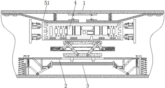
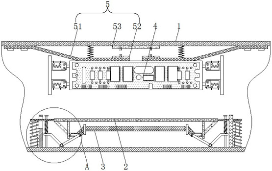
[0024] see Figure 1-4 , an electro-acoustic transducer with multiple impact protection, including a housing 1, the inside of the housing 1 is slidably connected to a bracket 2, and the bracket 2 is slidably connected to the housing 1 in the vertical direction for the vibrating membrane 3 Support and buffer protection, the inside of the bracket 2 is slidingly connected to the vibrating membrane 3, the vibrating membrane 3 and the bracket 2 are slidingly connected in the vertical direction, the upper part of the vibrating membrane 3 is electrically connected to the transducer assembly 4, and the inside of the housing 1 A first shock protector 5 is provided to cooperate with the second shock protector 6 to provide shock protection for the vibrating membrane 3 and the transducer assembly 4 .

[0025] The first impact protection 5 includes a shrapnel 51. The shrapnel 51 adopts a Z-shaped design and is located on the surface of the transducer assembly 4. The end away from the trans...

Embodiment 2

[0028] see Figure 1-4 , an electro-acoustic transducer with multiple impact protection, including a housing 1, the inside of the housing 1 is slidably connected to a bracket 2, and the bracket 2 is slidably connected to the housing 1 in the vertical direction for the vibrating membrane 3 Support and buffer protection, the inside of the bracket 2 is slidingly connected to the vibrating membrane 3, the vibrating membrane 3 and the bracket 2 are slidingly connected in the vertical direction, the upper part of the vibrating membrane 3 is electrically connected to the transducer assembly 4, and the inside of the housing 1 A first shock protector 5 is provided to cooperate with the second shock protector 6 to provide shock protection for the vibrating membrane 3 and the transducer assembly 4 .

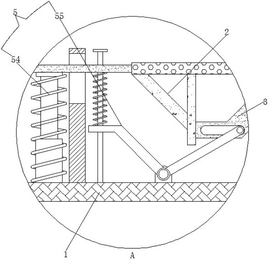
[0029] Including the second shock protector 6, which cooperates with the first shock protector 5 to provide shock protection for the vibrating membrane 3 and the transducer assembly 4. A sl...

Embodiment 3

[0032] see Figure 1-4 , an electro-acoustic transducer with multiple impact protection, including a housing 1, the inside of the housing 1 is slidably connected to a bracket 2, and the bracket 2 is slidably connected to the housing 1 in the vertical direction for the vibrating membrane 3 Support and buffer protection, the inside of the bracket 2 is slidingly connected to the vibrating membrane 3, the vibrating membrane 3 and the bracket 2 are slidingly connected in the vertical direction, the upper part of the vibrating membrane 3 is electrically connected to the transducer assembly 4, and the inside of the housing 1 A first shock protector 5 is provided to cooperate with the second shock protector 6 to provide shock protection for the vibrating membrane 3 and the transducer assembly 4 .

[0033] The first impact protection 5 includes a shrapnel 51. The shrapnel 51 adopts a Z-shaped design and is located on the surface of the transducer assembly 4. The end away from the trans...


PUM


Abstract

The invention provides an electroacoustic transducer with multiple impact protection, and relates to the technical field of electroacoustic transducers. The electroacoustic transducer with multiple impact protections comprises a second impact protector, a sliding plate is arranged in the second impact protector, a first buffer connecting rod is slidably connected in the sliding plate, a buffer spring is arranged on the surface of the first buffer connecting rod, and a second buffer connecting rod is rotatably connected to the end, away from the sliding plate, of the first buffer connecting rod. According to the electroacoustic transducer with multiple impact protections, an elastic sheet and a transduction assembly are used in cooperation, impact buffering protection can be performed on the transduction assembly, and a first magnetic sheet and a second magnetic sheet are used in cooperation, so that deformation of the elastic sheet can be relieved, irreversible deformation of the elastic sheet can be prevented, and the impact protection effect of the elastic sheet can be guaranteed; a first buffer connecting rod and a second buffer connecting rod are used in cooperation with the buffer spring, secondary impact protection can be carried out on the transduction assembly, and the anti-impact protection effect of the transduction assembly can be effectively improved.

Description

technical field [0001] The invention relates to the technical field of electroacoustic transducers, in particular to an electroacoustic transducer with multiple impact protection. Background technique [0002] An electroacoustic transducer is a device used to receive an electrical signal and convert the electrical signal into an acoustic signal, or receive an acoustic signal and convert the acoustic signal into an electrical signal. When the electroacoustic transducer is dropped or bumped When impacting, the internal transducer device will move relative to each other, and may come into contact with the shell of the transducer, which will have a certain impact on the transducer device. Therefore, it is necessary to protect the transducer device inside the electro-acoustic transducer against impact. Protection, the structure of the anti-shock mechanism inside the existing electro-acoustic transducer is relatively simple, and the buffer movement stroke is relatively large, whic...

Claims


Application Information

Patent Timeline
IPC IPC(8): H04R1/02H04R7/02F16F15/02F16F15/04F16F15/06
CPCH04R1/02H04R7/02F16F15/022F16F15/03F16F15/046F16F15/06
Inventor 金卫国董卫童
Owner GAOYOU HUASHENG ELECTRONICS
Why Eureka
Try Eureka