Experimental device for simulating evaporation and combustion of liquid drops of engine under high-temperature and high-pressure conditions

A high-temperature, high-pressure, droplet evaporation technology, applied in chemical analysis by combustion, internal combustion engine test, investigation stage/state change, etc., can solve the problem of large size difference, less research on spontaneous combustion characteristics, changing droplet heat transfer conditions, etc. question

Pending Publication Date: 2022-02-15
XI AN JIAOTONG UNIV
View PDF0 Cites 2 Cited by
  • Summary
  • Abstract
  • Description
  • Claims
  • Application Information

AI Technical Summary

Problems solved by technology

At present, research on droplet evaporation and spontaneous combustion experiments mainly focuses on the high-temperature and low-pressure evaporation characteristics and spontaneous combustion characteristics of droplets, while there are few studies on the evaporation characteristics and spontaneous combustion characteristics of droplets under high-temperature and high-pressure conditions; at the same time, the methods of droplet generation mainly Using the hanging drop method, the diameter of the droplets produced is generally greater than 1mm, which is quite different from the size of the droplets in the actual engine, and the material of the hanging droplets will change the shape of the droplets and the heat exchange conditions between the droplets and the environment

Method used


Image

  • Experimental device for simulating evaporation and combustion of liquid drops of engine under high-temperature and high-pressure conditions
  • Experimental device for simulating evaporation and combustion of liquid drops of engine under high-temperature and high-pressure conditions
  • Experimental device for simulating evaporation and combustion of liquid drops of engine under high-temperature and high-pressure conditions

Examples


Embodiment Construction

[0025] The present invention will be further described below in conjunction with the accompanying drawings.

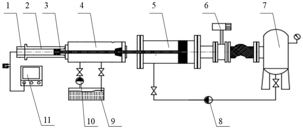
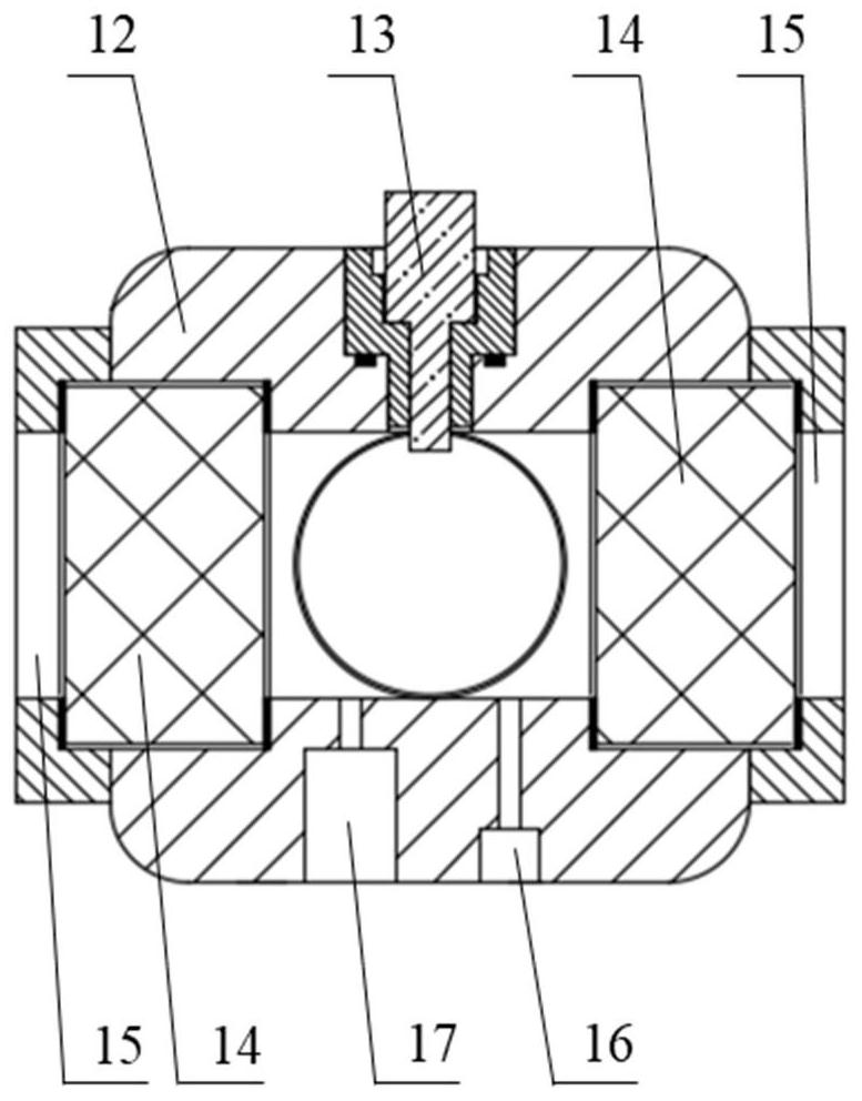
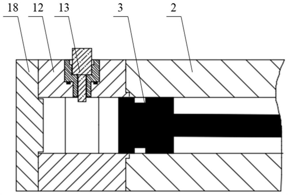
[0026] see Figure 1 to Figure 4 , the present invention provides an experimental device for simulating the evaporation and combustion of droplets under high temperature and high pressure conditions of an engine, including a visual combustion chamber 1, a compression section 2, a piston linkage mechanism 3, a hydraulic section 4, a driving section 5, an electric butterfly valve 6, a storage The air tank 7, the high-pressure air pump 8, the hydraulic oil tank 9 with the hydraulic oil pump 10, and the signal generating and collecting system 11 are composed. The visible combustion chamber 1 is composed of a combustion chamber main body 12, a quartz window 14, a quartz window cover 15, an intake and exhaust port 16, a pressure sensor hole 17 and an injector installation hole. The microscopic imaging system is composed of a backlight 21 , a quartz window 14 , a telephoto m...


PUM


Abstract

The invention discloses an experimental device for simulating evaporation and combustion of liquid drops of an engine under high-temperature and high-pressure conditions. The experimental device comprises a high-temperature and high-pressure visual rapid compressor experimental system, an oil sprayer liquid drop generation system, a signal generation and acquisition system and a microscopic imaging system. According to the high-temperature and high-pressure visual rapid compressor experiment system, hydraulic braking is driven by air pressure, a piston connecting rod mechanism is driven by compressed air to rapidly compress gas in a cylinder, and a uniform high-temperature and high-pressure environment is formed in a visual combustion chamber; the signal generation and acquisition system is used for controlling a quick compressor to act and giving a high-speed camera trigger signal and a combustion chamber dynamic pressure acquisition signal of the microscopic imaging system; the oil sprayer liquid drop generation system is used for supplying a certain number of submillimeter discrete liquid drops to the combustion chamber; and the microscopic imaging system is used for obtaining liquid drop process image information in the visual combustion chamber. The device is beneficial to research on evaporation characteristics and spontaneous combustion characteristics of liquid drops and establishment of a numerical model under high-temperature and high-pressure conditions.

Description

technical field [0001] The invention belongs to the technical field of internal combustion engines, and in particular relates to an experimental device for simulating the evaporation and combustion of liquid droplets under high temperature and high pressure conditions of the engine. Background technique [0002] As an important energy source, the chemical energy released by the combustion of liquid fuel is widely used in various power equipment and is an important energy source for various internal combustion engines. The combustion of liquid fuel is a complex heterogeneous two-phase reaction flow process, which mainly includes the preparation stage of combustible mixture and the ignition and combustion stage of mixture. Under the conditions of high temperature and high pressure, the chemical reaction speed is very fast, and the combustion rate of liquid fuel is mainly limited by the preparation process of combustible mixture, such as the evaporation process of fuel and the ...

Claims


Application Information

Patent Timeline
IPC IPC(8): G01N31/12G01N25/02G01M15/04
CPCG01N31/12G01N25/02G01M15/04
Inventor 汤成龙麦棹铭李昱武颖韬黄佐华
Owner XI AN JIAOTONG UNIV
Why Eureka
Try Eureka