
Electromagnetic valve power supply circuit and adjusting method thereof

A technology of power supply circuit and solenoid valve, which is applied in the direction of valve details, valve device, valve operation/release device, etc., can solve the problems of low control accuracy, large reverse voltage, and weak dynamic adjustment ability, and achieve increased The effect of transmission efficiency, small output ripple, and strong dynamic adjustment ability

Active Publication Date: 2022-02-15
SOUTHWEAT UNIV OF SCI & TECH
View PDF11 Cites 0 Cited by
  • Summary
  • Abstract
  • Description
  • Claims
  • Application Information

AI Technical Summary

Problems solved by technology

[0003] The purpose of the present invention is to overcome the problems of large reverse voltage, weak dynamic adjustment ability and low control precision of the existing solenoid valve drive circuit, and provide a solenoid valve power supply circuit and its adjustment method

Method used


Image

  • Electromagnetic valve power supply circuit and adjusting method thereof
  • Electromagnetic valve power supply circuit and adjusting method thereof
  • Electromagnetic valve power supply circuit and adjusting method thereof

Examples


Embodiment 1

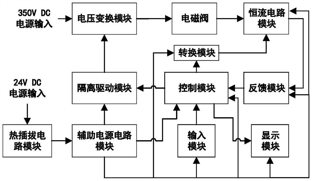
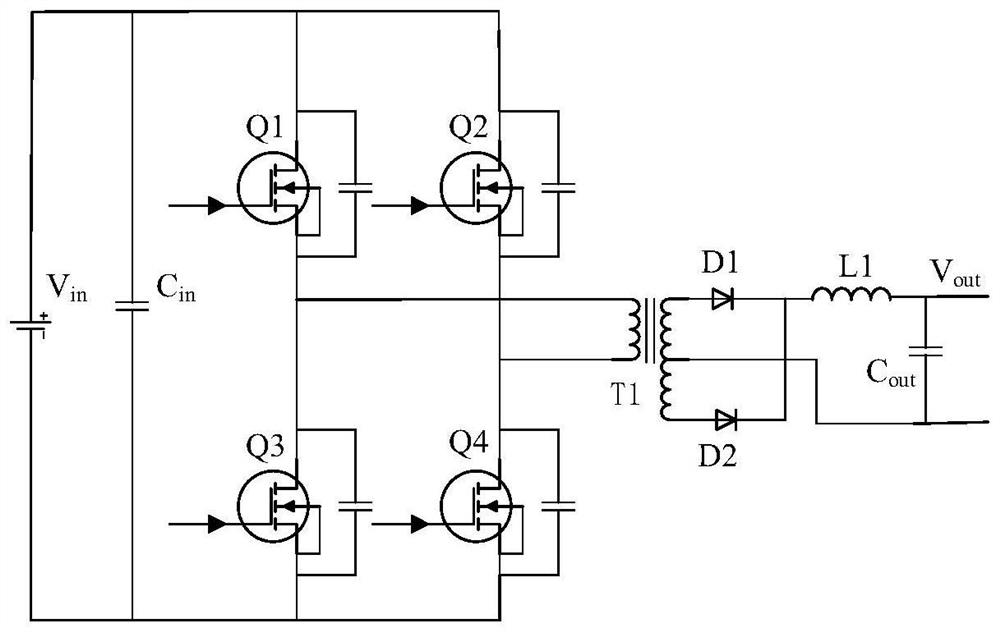
[0040] For the convenience of understanding the method of the present invention, with figure 1Taking the solenoid valve drive circuit as an example, the structure and working principle of the solenoid valve drive circuit are described, and a high-sensitivity solenoid valve power supply circuit and its adjustment method are provided. The drive circuit specifically includes a voltage conversion module, an isolation drive module, Control module, conversion module, constant current circuit module, feedback module, input module, display module, hot-swappable circuit module and auxiliary power circuit module. The input module is specifically a button, which is used to set the expected value of the output current of the constant current circuit module and dynamically adjust the driving power. The conversion module is specifically a DA converter, which is used to convert the digital reference signal output by the control module into an analog reference signal. The display module is s...

Embodiment 2

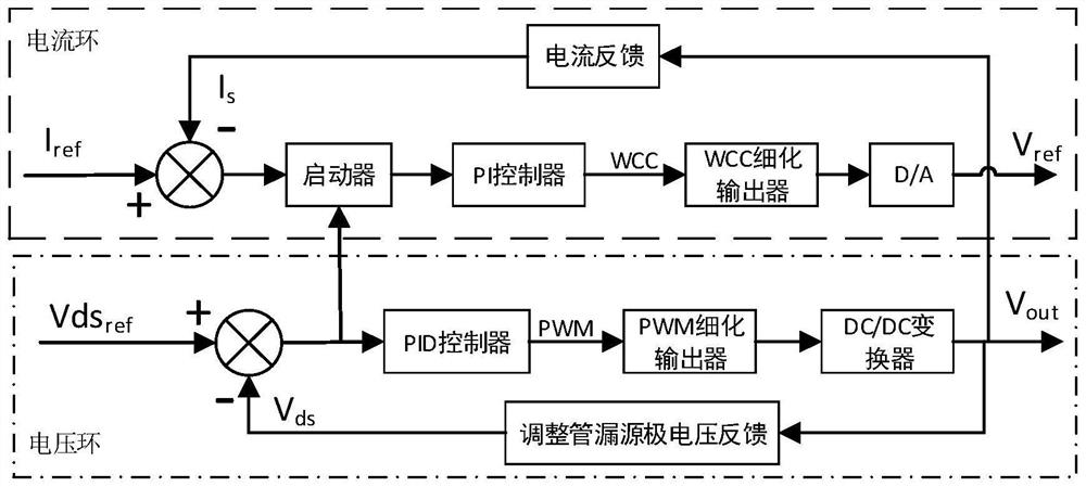
[0053] Such as Figure 5 As shown, the purpose of the present invention is to overcome the problems of large reverse voltage, weak dynamic adjustment ability, and low control precision of the existing solenoid valve drive circuit, and provide a constant current adjustment method for the solenoid valve. According to the constant current drive circuit of the solenoid valve The parameter information refines the output current of the solenoid valve constant current drive circuit to avoid large reverse voltage, strong dynamic adjustment ability, and high control precision. Wherein, the circuit parameter information includes the feedback current, the drain-source voltage information of the regulator tube in the voltage loop inside the solenoid valve constant current drive circuit. More specifically, as Image 6 As shown, the method of the present invention is implemented based on the voltage envelope current technology. In the figure, the mark 1 is the output voltage waveform of th...


PUM


Abstract

The invention discloses an electromagnetic valve power supply circuit and an adjusting method thereof, and belongs to the technical field of power supply control. The method specifically comprises the steps of carrying out real-time adjustment of the output voltage of an electromagnetic valve constant-current drive circuit according to parameter information of the electromagnetic valve constant-current drive circuit, and carrying out the refining processing of the output current of the electromagnetic valve constant-current drive circuit. The electromagnetic valve power supply circuit and the adjusting method thereof have the advantages that: stable constant current can be rapidly and finely output, the current adjusting precision is high, the reverse voltage generated by an electromagnetic valve is small, and the service life of an electronic device is prolonged; and the system loss can be reduced to the greatest extent, and the transmission efficiency is improved.

Description

technical field [0001] The invention relates to the technical field of power supply control, in particular to a solenoid valve power supply circuit and an adjustment method thereof. Background technique [0002] As a basic component of automation, solenoid valves are widely used in various industrial scenarios. For example, in nuclear reactors, the operation of starting, stopping, power regulation, and accident reverse insertion of the reactor is realized by controlling the solenoid valve to adjust the position of the control rod. When the solenoid valve is energized, its coil generates electromagnetic force to lift the closing member from the valve seat to open the valve. When the valve is opened, the armature continues to absorb, the stroke distance is reduced to the minimum, and the electromagnetic force reaches the maximum. When the armature is in the state, the extra power passes through. Coil resistance is converted into heat energy, and the long-term accumulation of h...

Claims


Application Information

Patent Timeline
Patent Type & Authority Applications(China)
IPC IPC(8): F16K31/06
CPCF16K31/0675
Inventor 朱玉颖朱玉玉李佳鑫康玉宽
Owner SOUTHWEAT UNIV OF SCI & TECH
Learn More