
Construction method of high pier column straining beam

A construction method, high pier column technology, applied in the direction of bridges, bridge parts, bridge construction, etc., can solve the problems of slow construction speed, safety accidents, long construction period, etc., reduce the number of materials and machinery, speed up construction speed, shorten The effect of the construction period

Pending Publication Date: 2022-02-15
MCC COMM CONSTR GRP CO LTD
View PDF15 Cites 2 Cited by
  • Summary
  • Abstract
  • Description
  • Claims
  • Application Information

AI Technical Summary

Problems solved by technology

After the tie beam construction is completed, the climbing formwork system on the side of the high pier column tie beam needs to be removed, which is prone to safety accidents and has a long construction period
This construction method has high cost and slow construction speed, and it is difficult to guarantee the construction quality

Method used


Image

  • Construction method of high pier column straining beam
  • Construction method of high pier column straining beam
  • Construction method of high pier column straining beam

Examples


Embodiment Construction

[0026] The construction method of the high pier column system beam and the embodiment of the construction method thereof will be described below with reference to the accompanying drawings. As those skilled in the art would realize, the described embodiments may be modified in various different ways, all without departing from the spirit and scope of the present invention. Accordingly, the drawings and description are illustrative in nature and not intended to limit the scope of the claims. Also, in this specification, the drawings are not drawn to scale, and like reference numerals denote like parts.

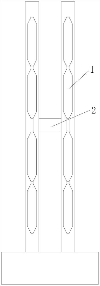
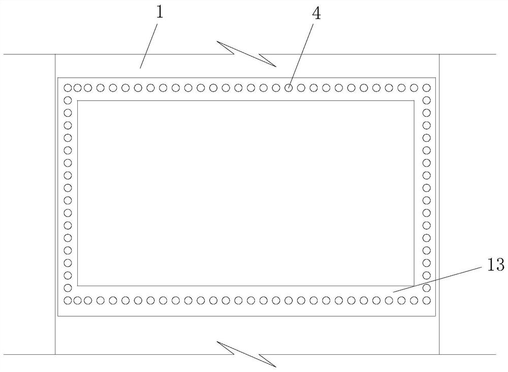
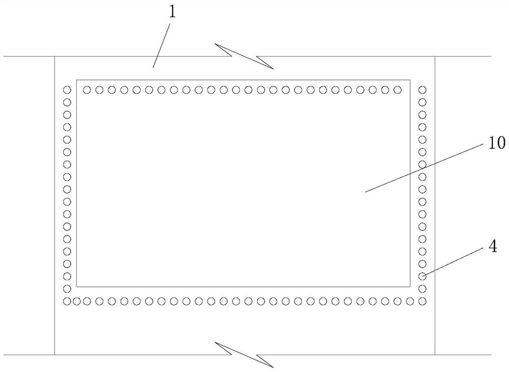
[0027] figure 1 It is a structural schematic diagram of a high pier involved in an embodiment of the present invention. In the figure, a tie beam 2 connecting the two high pier columns 1 is arranged between the two high pier columns 1 . In the traditional method, formwork needs to be set up at the tie beam 2, and the steel bar binding and concrete pouring of the tie beam 2 a...


PUM


Abstract

The invention discloses a construction method of a high pier column straining beam. The construction method comprises the steps that a first hole opposite to a longitudinal bar of the straining beam in position is formed in a high pier column; a groove-shaped straining beam supporting structure is manufactured, a second hole opposite to a straining beam longitudinal bar in position is preset in the straining beam supporting structure, and a positioning structure opposite to a straining beam stirrup in position is preset on the inner side wall; the straining beam supporting structure is hoisted to the preset height between the high pier columns, an opening of the straining beam supporting structure is made to face upwards, prestressed tendons are arranged in the first holes and the second holes which are opposite in position in a penetrating mode, the prestressed tendons are tensioned, and after the prestressed tendons are fixed, cement paste is injected into the holes where the prestressed tendons are located; after the cement paste reaches the preset strength, steel bars penetrate into the remaining first holes, stirrups of the straining beam are bound, and the stirrups are bound to the steel bars and the positioning structures; and concrete is poured into the straining beam supporting structure. According to the construction method of the high pier column straining beam, the construction quality is guaranteed, meanwhile, the construction cost can be reduced, and the construction speed is increased.

Description

technical field [0001] The invention relates to the technical field of bridge construction, in particular to a construction method for high pier columns and beams. Background technique [0002] During the construction of highways and railways, bridges often need to be erected, especially in places such as high mountains and canyons, higher bridges need to be constructed and erected. In the construction of such bridges, high piers are often used as supporting structures. When the bridge deck is wide, at least two high piers need to be arranged along the transverse direction of the bridge deck. In order to improve the stress-bearing structure of the high pier columns in the horizontal direction and strengthen the overall rigidity of the high pier columns, a tie beam will be set between the adjacent high pier columns to connect the horizontally adjacent high pier columns into a whole. [0003] At present, the commonly used construction method of high pier columns and tie beam...

Claims


Application Information

Patent Timeline
Patent Type & Authority Applications(China)
IPC IPC(8): E01D21/00E01D19/00E01D19/02
CPCE01D21/00E01D19/00E01D19/02
Inventor 刘思谋
Owner MCC COMM CONSTR GRP CO LTD
Learn More