
Steel wire winding device

A winding device and steel wire technology, which is applied in the directions of transportation and packaging, delivery of filamentous materials, thin material processing, etc., can solve the problems of wasting reel space, chaotic winding of steel wires, and intertwining of steel wires, etc., so as to facilitate wire arrangement and Winding, quick change, uniform winding effect

Inactive Publication Date: 2022-02-15
南通华东特种钢丝有限公司
View PDF0 Cites 2 Cited by
  • Summary
  • Abstract
  • Description
  • Claims
  • Application Information

AI Technical Summary

Problems solved by technology

[0002] At present, steel wire is one of the four types of steel plates, tubes, profiles, and wires. It is a reprocessed product made of hot-rolled wire rods and cold-drawn. The main processes of steel wire production include raw material selection, iron oxide removal, drying, Coating treatment, heat treatment, wire drawing, coating treatment, etc. After the steel wire is formed, it needs to be wound on the reel. The current winding method is to directly drive the reel to wind the steel wire through the motor, and the steel wire is wound on the reel. It often causes a large amount of steel wires to be wound in the middle of the reel and fewer steel wires on both sides, so that the coiled steel wires are distributed in a shuttle shape on the reel, which wastes the space of the reel, and it is easy to cause the steel wires to be entangled with each other during use. Therefore, we propose A wire winding device

Method used


Image

  • Steel wire winding device
  • Steel wire winding device
  • Steel wire winding device

Examples


Embodiment Construction

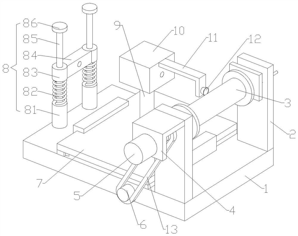
[0030] The following is attached Figure 1-4 The application is described in further detail.

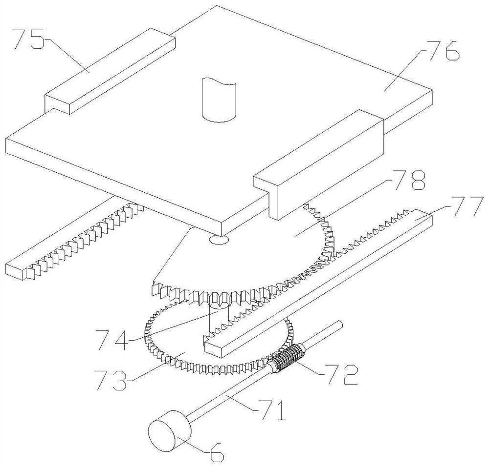
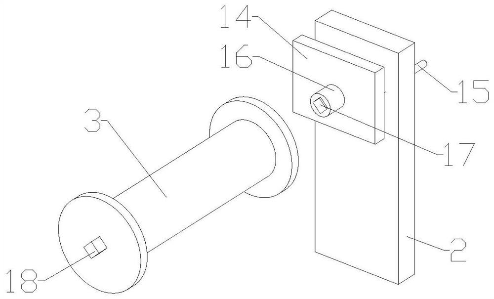
[0031] The embodiment of the present application discloses a steel wire winding device. refer to Figure 1-4 , a steel wire winding device, comprising a base 1, characterized in that: two fixed plates 2 are fixedly installed on the top of one end of the base 1, a reel 3 is installed between the tops of the fixed plates 2, and a motor is fixedly installed on the outer wall of one fixed plate 2 Seat 4, the motor 5 is fixedly installed on the outer wall of the motor seat 4, the output shaft of the motor 5 is connected to the reel 3, and the cable arrangement mechanism 7 is installed on the base 1 next to the fixed plate 2, and the cable arrangement mechanism 7 and the output shaft of the motor 5 are installed The pulley 6 is connected with the transmission belt 13 between the pulleys 6, the top of the cable arrangement 7 is fixedly installed with a column 9, the top of the column 9 is...


PUM


Abstract

The invention relates to a steel wire winding device, which comprises a base, wherein two fixing plates are installed at the top of one end of the base, a winding drum is installed between the tops of the fixing plates, a motor seat is installed on the outer wall of one fixing plate, a motor is installed on the outer wall of the motor seat and connected with the winding drum, a wire arranging mechanism is installed on the base beside the fixing plates, belt pulleys are arranged on the output shafts of the wire arranging mechanism and the motor, a transmission belt is sleeved between the belt pulleys, the top of the wire arranging mechanism is fixedly provided with a stand column, the top of the stand column is fixedly provided with a wire guiding block, the outer wall, close to the fixing plate, of the wire guiding block is fixedly provided with a lead wire frame, the top of the other end of the base is provided with a tightening mechanism, and a steel wire sequentially penetrates through the tightening mechanism, the wire guiding block and the lead wire frame and is connected with the winding drum. According to the invention, when a motor drives a winding drum to wind a steel wire, a wire arranging mechanism is synchronously driven by a transmission belt and belt pulleys to move, the wire arranging mechanism axially reciprocates along the winding drum and rotates for a circle in the winding drum, and the moving distance of the wire arranging mechanism is equal to the diameter of the steel wire, so that the steel wire is wound on the winding drum circle by circle, and uniform winding is achieved.

Description

technical field [0001] The present application relates to the technical field of steel wire processing, in particular to a steel wire winding device. Background technique [0002] At present, steel wire is one of the four major types of steel plates, tubes, profiles, and wires. It is a reprocessed product made of hot-rolled wire rods and cold-drawn. The main processes of steel wire production include raw material selection, iron oxide removal, drying, Coating treatment, heat treatment, wire drawing, coating treatment, etc. After the steel wire is formed, it needs to be wound on the reel. The current winding method is to directly drive the reel to wind the steel wire through the motor, and the steel wire is wound on the reel. It often causes a large amount of steel wires to be wound in the middle of the reel and fewer steel wires on both sides, so that the wound steel wires are distributed in a shuttle shape on the reel, which wastes the space of the reel, and it is easy to c...

Claims


Application Information

Patent Timeline
Patent Type & Authority Applications(China)
IPC IPC(8): B65H54/553B65H54/44B65H54/28B65H57/06B65H57/28B65H67/04B65H59/10
CPCB65H54/553B65H54/44B65H54/28B65H57/06B65H57/28B65H67/0411B65H59/10B65H2701/30
Inventor 沈国庆沈兴达
Owner 南通华东特种钢丝有限公司
Learn More