
Special 3D printing equipment for printing hollow cylindrical component and printing method thereof

A technology of 3D printing and special equipment, applied in the field of additive manufacturing, can solve problems such as days or even a month, product deformation out of tolerance, no special equipment, etc., to improve production efficiency, simple structure, and improve product quality Effect

Pending Publication Date: 2022-02-15
苏州三峰激光科技有限公司
View PDF0 Cites 3 Cited by
  • Summary
  • Abstract
  • Description
  • Claims
  • Application Information

AI Technical Summary

Problems solved by technology

However, metal 3D printers on the market do not have dedicated equipment for such products
When the existing 3D printing equipment prints these hollow cylindrical large-scale structural parts, it often takes more than ten days or even a month to print a product. The product has gradually released stress during the long-term printing process, resulting in product failure Final deformation out of tolerance

Method used


Image

  • Special 3D printing equipment for printing hollow cylindrical component and printing method thereof
  • Special 3D printing equipment for printing hollow cylindrical component and printing method thereof
  • Special 3D printing equipment for printing hollow cylindrical component and printing method thereof

Examples


Embodiment 1

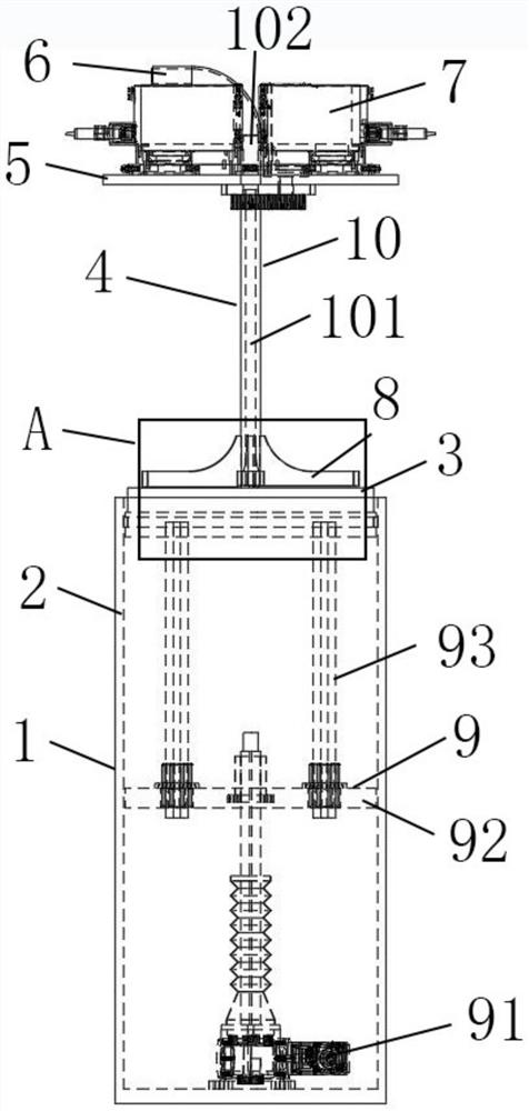
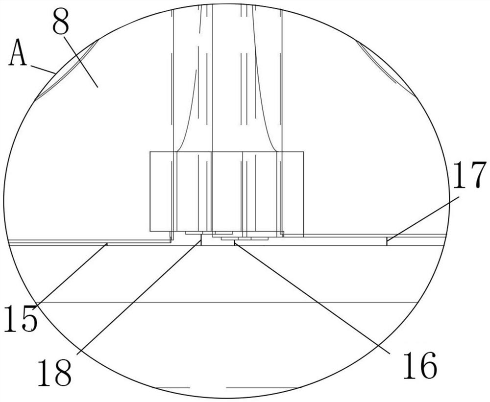
[0059] Such as figure 1 As shown, a 3D printing special equipment for printing hollow cylindrical components, including

[0060] A printing device 1, the printing device includes a device housing 2 and a printing substrate 3, the printing substrate is located inside the device housing and moves up and down inside the device housing, and the printing substrate is used to carry 3D Printing powder and formed products;

[0061] A powder spreading device 4, the powder spreading device is suspended above the printing device, the powder spreading device includes a whole platform 5, a powder feeding pipeline 6, several laser vibrating mirrors 7 and several scrapers 8,

[0062] The powder feeding pipeline is in communication with each of the scrapers, and the powder feeding pipeline is used to provide 3D printing powder to the scrapers;

[0063] Several of the laser galvanometers are located above the whole platform, and the laser galvanometers are used to emit laser light to irradia...

Embodiment 2

[0082] This embodiment is carried out on the basis of the first embodiment, and the similarities with the first embodiment will not be repeated.

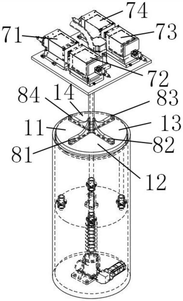
[0083] Such as Figure 2-Figure 3 As shown, the number of the scrapers is the same as the number of the laser vibrating mirrors, which are 4; the 4 scrapers are respectively a first-level step scraper 81, a second-level step scraper 82, a third-level step scraper 83 and a fourth-level step scraper. Step scraper 84; the included angle between two adjacent scrapers is 90°; 4 scrapers divide the printing substrate into printing area A11, printing area B12, printing area C13 and printing area D14; 4 The laser vibrating mirrors are respectively laser vibrating mirror A71, laser vibrating mirror B72, laser vibrating mirror C73 and fourth laser D74, the laser vibrating mirror A is located directly above the printing area A, and the laser vibrating mirror B Located directly above the printing area B, the laser vibrating mirror C is located...

Embodiment 3

[0087] This embodiment is carried out on the basis of Embodiment 1 or Embodiment 2, and the similarities with Embodiment 1 or 2 will not be repeated.

[0088] This embodiment relates to a 3D printing method for printing hollow cylindrical components, using the 3D printing special equipment described in Embodiment 1 or 2, including the following steps:

[0089] S1. Establish a three-dimensional structure model of the product to be printed, slice and layer the three-dimensional structure model, and import the layered data into the special equipment for 3D printing;

[0090] S2. Select the operating parameters and the number of partitions of the 3D printing special equipment through the layer thickness set in step S1, including the laser pulse width, power density, beam focal spot, scraper speed, printing substrate moving speed, printing layer of the laser galvanometer Thickness and printing speed;

[0091] S3. Perform initialization according to the operating parameters selecte...


PUM

PropertyMeasurementUnit
thicknessaaaaaaaaaa

Abstract

The invention relates to special 3D printing equipment for printing a hollow cylindrical component and a printing method thereof. The equipment comprises a printing device and a powder laying device, the printing device comprises a device shell and a printing substrate, and the printing substrate is located in the device shell and moves up and down in the device shell; the powder laying device is hung above the printing device, and the powder laying device comprises a platform whole body, a powder feeding pipeline, a plurality of laser galvanometers and a plurality of scrapers; the plurality of scrapers are rotationally connected with the whole platform; and the distances between the lower end faces of the scrapers and the printing substrate are different. According to the invention, the plurality of rotatable scrapers and the corresponding number of laser galvanometers are adopted, the printing substrate is divided into a plurality of printing areas, partitioned laser and printing are realized, stepped rotary powder spreading is realized by setting the continuous change of the distance between each scraper and the printing substrate, the printing efficiency can be improved by about 16 times, and finally the product quality is improved.

Description

technical field [0001] The invention relates to the technical field of additive manufacturing, in particular to a 3D printing special equipment for printing hollow cylindrical components and a printing method thereof. Background technique [0002] At present, the mainstream metal 3D printing technology SLM (selective laser melting technology) is an emerging additive manufacturing technology. The machine operator selects and sinters the powder of the working platform according to the CAD graphic data, and the high-energy focused laser beam makes the powder completely melt and tightly bond. The parts prepared by laser selective melting technology can reach the theoretical density level, which is a rapid prototyping technology with great development prospects, especially in aerospace, mold, oil pipeline and other fields. [0003] At present, in the fields of aerospace, oil pipelines, and gas turbines, there are many hollow cylindrical large-scale structural parts that can be d...

Claims


Application Information

Patent Timeline
Patent Type & Authority Applications(China)
IPC IPC(8): B22F12/00B22F10/28B22F12/67B22F10/85B22F10/364B22F10/38B22F12/45B22F12/50B22F12/30B33Y10/00B33Y30/00
CPCB22F12/00B22F10/28B22F12/67B22F10/85B22F10/364B22F10/38B22F12/45B22F12/50B22F12/30B22F12/222B33Y10/00B33Y30/00Y02P10/25
Inventor 孙明丰张达明施春宇杨琢
Owner 苏州三峰激光科技有限公司
Learn More