
Display panel and preparation method thereof

A display panel and substrate technology, which is applied in the manufacture of semiconductor/solid-state devices, electrical components, diodes, etc., can solve the problems that affect the bending ability of flexible screens, the overall thickness of the polarizing module, and the overall reflectivity of the display panel. Display effect, eliminate stray light interference, low reflectivity effect

Pending Publication Date: 2022-02-11
BOE TECH GRP CO LTD
View PDF0 Cites 0 Cited by
  • Summary
  • Abstract
  • Description
  • Claims
  • Application Information

AI Technical Summary

Problems solved by technology

[0006] In view of the shortcomings of the existing methods, the present application proposes a display panel and its preparation method to solve the problems in the display panel of the prior art: the overall thickness of the polarizing module is too large, which affects the bending ability of the flexible screen or the overall display panel Technical problems with high reflectivity

Method used


Image

  • Display panel and preparation method thereof
  • Display panel and preparation method thereof
  • Display panel and preparation method thereof

Examples


Embodiment Construction

[0054] The present application is described in detail below, and examples of embodiments of the present application are shown in the drawings, wherein the same or similar reference numerals denote the same or similar components or components having the same or similar functions throughout. Also, detailed descriptions of known technologies will be omitted if they are not necessary to illustrate the features of the present application. The embodiments described below by referring to the figures are exemplary only for explaining the present application, and are not construed as limiting the present application.

[0055]Those skilled in the art can understand that, unless otherwise defined, all terms (including technical terms and scientific terms) used herein have the same meanings as commonly understood by those of ordinary skill in the art to which this application belongs. It should also be understood that terms, such as those defined in commonly used dictionaries, should be u...


PUM

PropertyMeasurementUnit
Wavelengthaaaaaaaaaa
Thicknessaaaaaaaaaa

Abstract

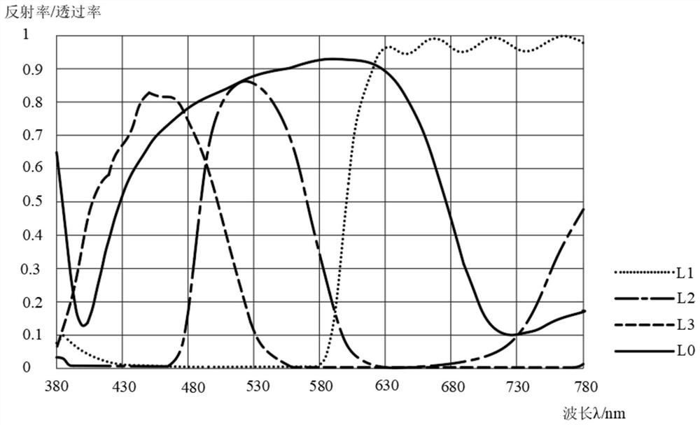
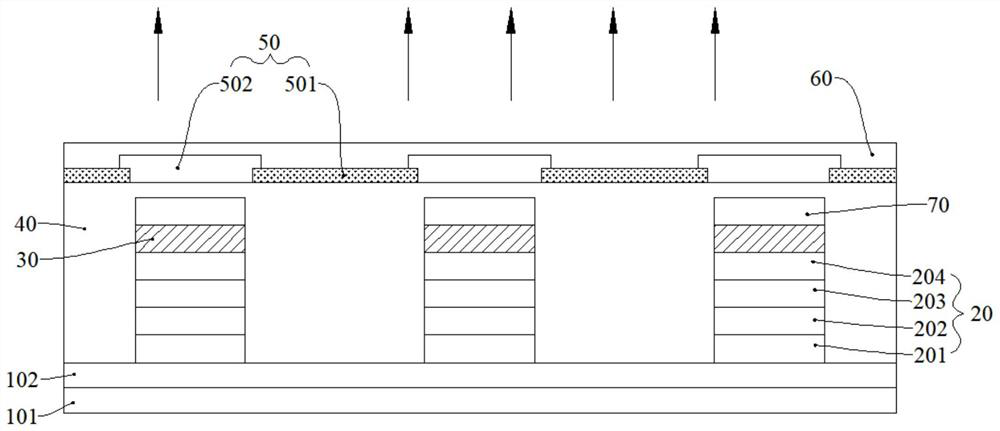
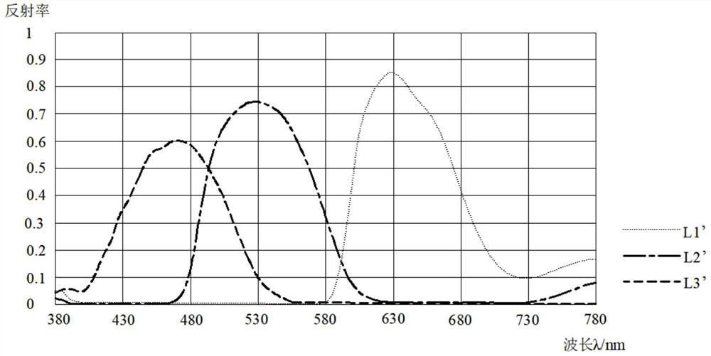
The embodiment of the invention provides a display panel and a preparation method thereof. The display panel comprises a substrate, a first filter layer arranged on one side of the substrate, and a second filter layer arranged on one side, far away from the substrate, of the first filter layer. The reflectivity of the display panel to the first light is not greater than 50%; and / or the reflectivity to the second light is not greater than 10%. The display panel provided by the embodiment of the invention has relatively high reflectivity to light within the wavelength range of the light-emitting layer and relatively low reflectivity to light outside the wavelength range of the light-emitting layer. When external light enters the display panel, light within the wavelength range of the light-emitting layer is reserved in a targeted mode and reflected to the light-emitting side of the display panel so as to improve the brightness of the display panel, light outside the wavelength range of the light-emitting layer is absorbed so as to eliminate stray light interference on the light-emitting side, the contrast ratio of the display panel is improved, and the display effect is improved.

Description

technical field [0001] The present application relates to the field of display technology, and in particular, the present application relates to a display panel and a manufacturing method thereof. Background technique [0002] Currently, there are usually two technical routes used in Organic Electroluminescence Display (OLED) display technology: one is to use a circular polarizer as a necessary component of an OLED touch display panel, and the other is to use a color filter (Color Filter, CF) replaces the polarizer (COE, Color Filter On Encapsulation) in OLED. [0003] In the first technical route, the main function of the circular polarizer is to reduce the reflectivity when external light is incident on the OLED surface, thereby improving contrast and readability under ambient light. Circular polarizers are generally attached to the packaging cover of the display panel, but the thickness of the overall module is relatively large. If it is applied to a flexible display de...

Claims


Application Information

Patent Timeline
IPC IPC(8): H01L27/32H01L51/52H01L51/56
CPCH10K59/38H10K59/12H10K50/86H10K71/00
Inventor 王和金汪炳伟王纯阳
Owner BOE TECH GRP CO LTD
Learn More