Automatic hob head in shield tunneling machine

A hob and shield machine technology, applied in mining equipment, earthwork drilling, tunnels, etc., can solve problems affecting tool change efficiency, consumption, and large physical strength

Pending Publication Date: 2022-02-11
SHANGHAI ROBOT IND TECH RES INST CO LTD +1
View PDF0 Cites 0 Cited by
  • Summary
  • Abstract
  • Description
  • Claims
  • Application Information

AI Technical Summary

Problems solved by technology

The weight of a single tool is nearly 200kg. The tool transfer operation will consume a lot of physical strength and affect the efficiency of the entire tool change

Method used


Image

  • Automatic hob head in shield tunneling machine
  • Automatic hob head in shield tunneling machine
  • Automatic hob head in shield tunneling machine

Examples


Embodiment Construction

[0026] In order to make the present invention more comprehensible, preferred embodiments are described in detail below with accompanying drawings.

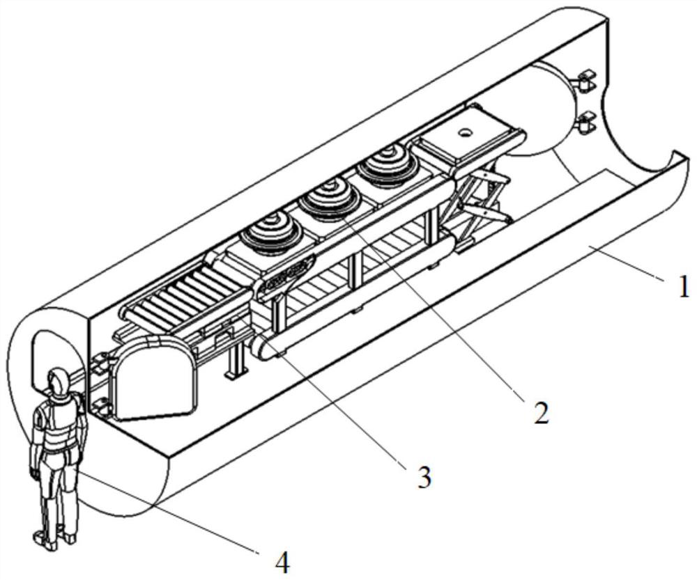
[0027] The invention provides an automatic hob frame inside a shield machine, such as figure 1 As shown, it includes a cabin body 1 and an automatic knife rest 3. The automatic tool holder 3 is installed inside the cabin body 1, the cabin body 1 has a columnar structure, and the cabin body 1 is connected with the shield machine body by screws.

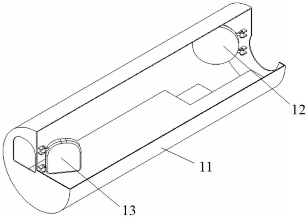
[0028] Such as figure 2 As shown, the cabin body 1 is made up of housing 11, front hatch door 12 and rear hatch door 13, and front hatch door 12 and rear hatch door 13 are all arranged on the housing 11, and front hatch door 12 is close to mud tank (or cutter head ), the rear hatch 13 is opposite to the front hatch 12, and the housing 11 is formed by roll bending welding of high-strength steel plates. The front hatch 12 and the rear hatch 13 are all in an open state outwardly. When it ...


PUM


Abstract

The invention discloses an automatic hob head in a shield tunneling machine, which is characterized by comprising a cabin body and an automatic tool rest, the automatic tool rest is arranged in the cabin body, and the automatic tool rest comprises a transverse moving platform structure, a conveying platform structure and a lifting platform structure which are sequentially connected in a conveying mode; the transverse moving platform structure is composed of a bottom-layer translation mechanism, a top-layer translation mechanism and a first conveying platform, the top-layer translation mechanism is arranged on the bottom-layer translation mechanism in a sliding mode, and the first conveying platform is arranged on the top-layer translation mechanism in a sliding mode. According to the invention, the new and old hobs in the shield tunneling machine can be automatically stored and taken, the circulation efficiency of the hobs is improved, the labor intensity of operators is reduced, and the working environment is improved.

Description

technical field [0001] The invention relates to an automatic hob frame inside a shield machine, belonging to the technical field of shield machines. Background technique [0002] During the use of the shield machine, the tool is prone to bluntness and damage, especially when encountering a hard soil environment, the tool wear will intensify. Considering the construction schedule and actual situation, it is often necessary to complete the tool replacement underground. [0003] During manual tool change operations, usually a group of 5 people, 2 of them complete the tool inspection, disassembly and installation in the mud tank, the other 2 people are in the manned gate, responsible for the conveying of the tool, and the remaining 1 person is responsible for other assistance outside the manned gate Operation. The weight of a single tool is nearly 200kg. The transfer operation of the tool will consume a lot of physical strength and affect the efficiency of the entire tool chan...

Claims


Application Information

Patent Timeline
Patent Type & Authority Applications(China)
IPC IPC(8): E21D9/08
CPCE21D9/08
Inventor 刘鹏袁建军郑凯宇王卫东李剑彤
Owner SHANGHAI ROBOT IND TECH RES INST CO LTD
Why Eureka
Try Eureka