
Drilling device for mine engineering blasting

A drilling device and technology for mining engineering, applied in drilling equipment and methods, drilling with explosives, earthwork drilling, etc. Simple, easy to use, easy to move effect

Inactive Publication Date: 2022-02-11
刘建法
View PDF0 Cites 1 Cited by
  • Summary
  • Abstract
  • Description
  • Claims
  • Application Information

AI Technical Summary

Problems solved by technology

Among them, manual punching is used, which is inefficient, time-consuming and laborious, and the effect of punching holes is also poor. Small-sized punching devices are used to punch holes. Because continuous vibrations will be generated when punching holes, these small-sized punching devices will vibrate. Offset occurs under the circumstances, resulting in a larger hole diameter, poor effect and inconvenient adjustment of the angle and height of the drilling, which needs to be improved

Method used


Image

  • Drilling device for mine engineering blasting
  • Drilling device for mine engineering blasting
  • Drilling device for mine engineering blasting

Examples


Embodiment 1

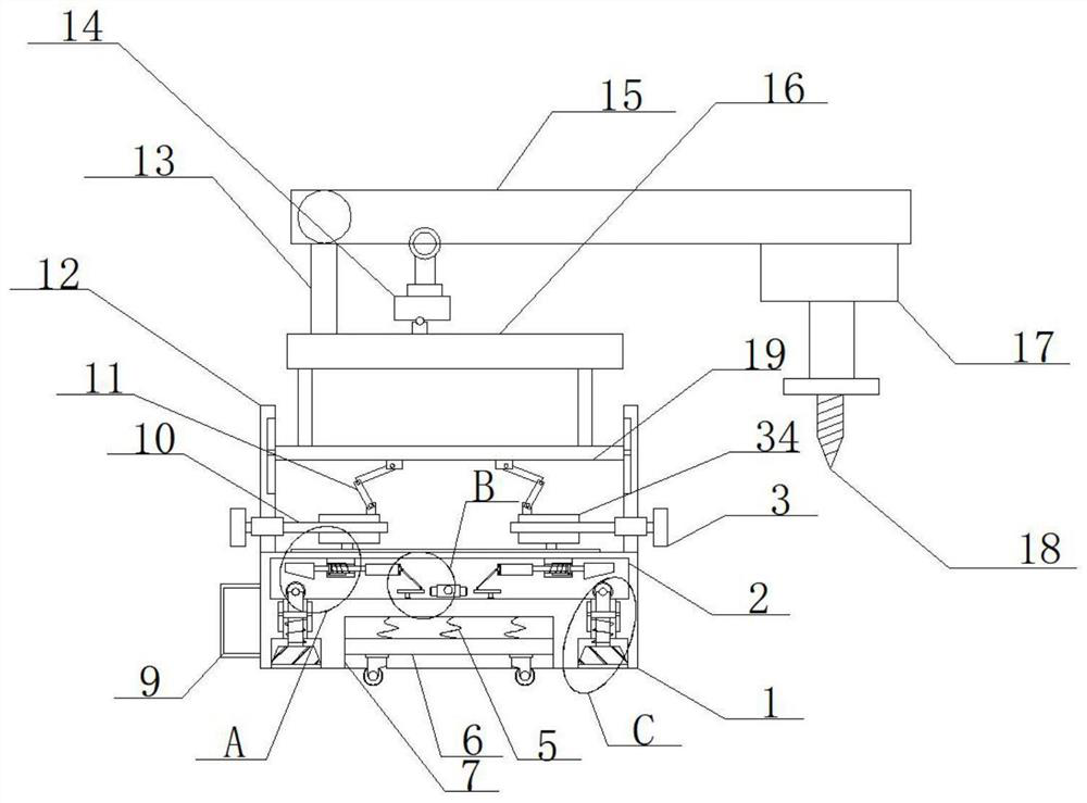
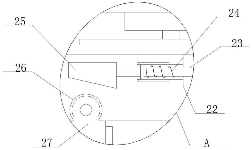
[0025] refer to Figure 1-5 , a drilling device for mine engineering blasting, including a base 1, the bottom of the base 1 is provided with two grooves 4 and an installation groove 7 and a square cavity 2 is opened inside, the installation groove 7 is located between the two grooves 4 and The inside is slidably installed with an engaging plate 6 along the vertical direction, and the four corners of the bottom of the engaging plate 6 are all rotated with universal wheels, and two through holes 8 are provided between the two grooves 4 and the square cavity 2. Vertical rods 27 are installed movably in the through holes 8, rollers 26 are mounted on the tops of the two vertical rods 27 and buffer blocks 33 are fixedly mounted on the bottom ends of the two vertical rods 27, and two plastic blocks are fixedly mounted on the top inner wall of the square cavity 2. 22 and two sector gears 30 are rotated on the bottom inner wall, and two plastic blocks 22 are provided with movable holes...

Embodiment 2

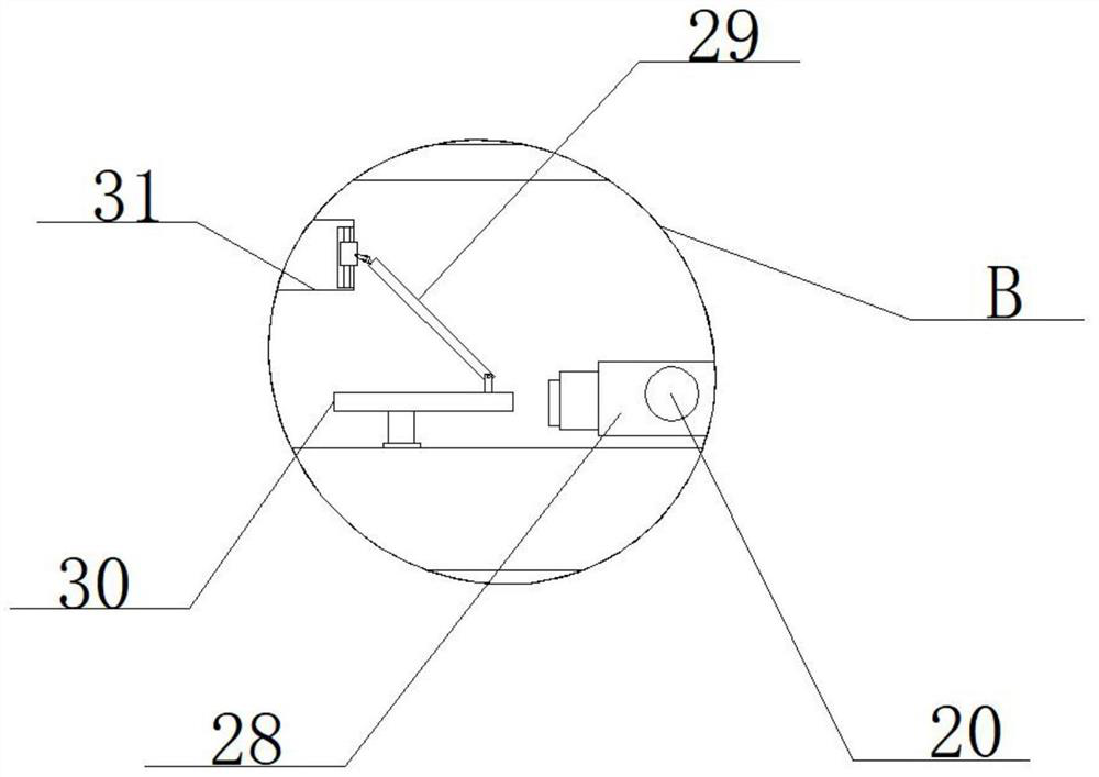
[0027] In the present invention, one side of the base 1 is threaded with a threaded rod 20, one end of the threaded rod 20 is rotatably mounted with a double-sided rack 28 located between two sector gears 30, and the other end is fixedly sleeved with a crank handle 21. Two double-sided racks 28 are all meshed with the sector gear 30, and the inward rotation of the threaded rod 20 is driven by turning the handle 21, which can drive the inward movement of the double-sided rack 28, and the double-sided rack 28 drives the The rotation of the two sector gears 30 can drive the rotation of the two connecting rods 29 , that is, the extrusion can drive the left and right separate movement of the two connecting blocks 31 .

[0028] In the present invention, multiple groups of buffer springs 5 ​​are fixedly installed between the connecting plate 6 and the top inner wall of the installation groove 7, and the multiple groups of buffer springs 5 ​​can play a shock-absorbing and buffering eff...

Embodiment 3

[0035] refer to Figure 1-5, a drilling device for mine engineering blasting, including a base 1, the bottom of the base 1 is provided with two grooves 4 and an installation groove 7 and a square cavity 2 is opened inside, the installation groove 7 is located between the two grooves 4 and An engaging plate 6 is slidably installed inside along the vertical direction, and universal wheels are mounted on the four corners of the bottom of the engaging plate 6 through bearings, and two through holes 8 are opened between the two grooves 4 and the square cavity 2, Both vertical rods 27 are movably installed in the two through holes 8, and the tops of the two vertical rods 27 are installed with rollers 26 and the bottom ends are fixedly welded with buffer blocks 33 by bearing rotation, and the top inner wall of the square cavity 2 is fixedly welded with Two plastic blocks 22 and two sector gears 30 are mounted on the inner wall of the bottom by bearing rotation, two plastic blocks 22 ...


PUM


Abstract

The invention belongs to the technical field of drilling devices, and particularly relates to a drilling device for mine engineering blasting, which comprises a base, two grooves and a mounting groove are formed in the bottom of the base, a square cavity is formed in the base, the mounting groove is positioned between the two grooves, and a connecting plate is slidably mounted in the mounting groove along the vertical direction; universal wheels are rotatably installed at the four corners of the bottom of the connecting plate, two through holes are formed between the two grooves and the square cavity, vertical rods are movably installed in the two through holes, rolling wheels are rotatably installed at the top ends of the two vertical rods, and buffer blocks are fixedly installed at the bottom ends of the two vertical rods; and two plastic blocks are fixedly mounted on the inner wall of the top of the square cavity, and two sector gears are rotationally mounted on the inner wall of the bottom of the square cavity. The drilling device for mine engineering blasting is simple in structure and convenient to use, the drilling device for mine engineering blasting is convenient to move, buffering and damping are facilitated, and the drilling angle and height can be adjusted.

Description

technical field [0001] The invention relates to the technical field of drilling devices, in particular to a drilling device for mine engineering blasting. Background technique [0002] When mining a mine, blasting means are usually used to blast the ore, so as to facilitate the collection of ore. In order to improve the blasting efficiency, it is usually necessary to drill the ore before blasting, and then blast the inside of the hole. Due to the complex road conditions in the mine, generally large-scale drilling vehicles cannot enter, and manual drilling or small drilling devices are usually used for drilling. Among them, manual punching is used, which is inefficient, time-consuming and laborious, and the effect of punching holes is also poor. Small-sized punching devices are used to punch holes. Because continuous vibrations will be generated when punching holes, these small-sized punching devices will vibrate. Offset occurs in the case of the drilled hole, resulting in ...

Claims


Application Information

Patent Timeline
IPC IPC(8): E21B7/02E21B7/04E21B3/02
CPCE21B7/007E21B7/02E21B7/04E21B3/02
Inventor 刘建法
Owner 刘建法
Learn More