
Structure and control method of bionic robot intelligent power arm with multiple sensors

A bionic robot and multi-sensor technology, applied in the structural field of the intelligent power arm of the bionic robot, can solve the problems of limited torque, limited practicality, and limited structural space, so as to automatically adjust the grasping force, improve the driving efficiency, and eliminate mutual effect of influence

Active Publication Date: 2022-02-11
北京联合伟世科技股份有限公司
View PDF7 Cites 1 Cited by
  • Summary
  • Abstract
  • Description
  • Claims
  • Application Information

AI Technical Summary

Problems solved by technology

Teaching and demonstration robot hands can be divided into pneumatic and electric according to the power source. Pneumatic components can adjust the pressure of compressed gas to make the strength of the hand meet the requirements of use under anthropomorphic conditions, but because the equipment that generates compressed gas cannot be configured independently In anthropomorphic robots, the practicability of this method is limited; there is a 5-axis anthropomorphic mechanical hand with a motor installed in the palm of the hand in an electric way. It has no practical value to transmit the output torque to the fingertips. On the other hand, the power motor located in the palm is restricted by the structural space, and the output torque is very limited. Third, because the three joints of a finger are controlled by a geared motor, There can only be a fixed trajectory, which cannot satisfy the complex functions of hand movements. The above three problems restrict the practicability of anthropomorphic robotic hands, and can only be used as teaching molds and toys

Method used


Image

  • Structure and control method of bionic robot intelligent power arm with multiple sensors
  • Structure and control method of bionic robot intelligent power arm with multiple sensors
  • Structure and control method of bionic robot intelligent power arm with multiple sensors

Examples


Embodiment 1

[0046]A structure of a bionic robot intelligent power arm with multiple sensors, including several knuckles and several finger roots, and also includes a power group and a pulling group, one end of the pulling group is fixedly connected to the power group, and the pulling group The other end of the knuckle is fixedly connected with the base of the finger.

[0047] In this embodiment, 20 motors and 20 flexible ropes are set.

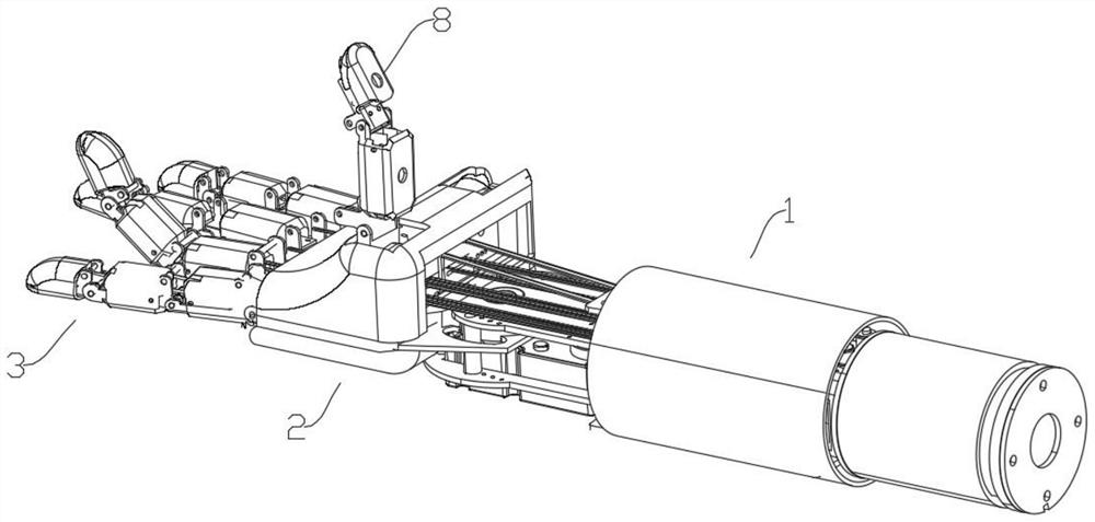
[0048] Such as figure 1 As shown, the structure of a bionic robot intelligent power arm with multiple sensors includes a forearm 1, a palm 2, 4 fingers 3 and a thumb 8. This kind of robotic hand is set up like a human hand and can serve humans.

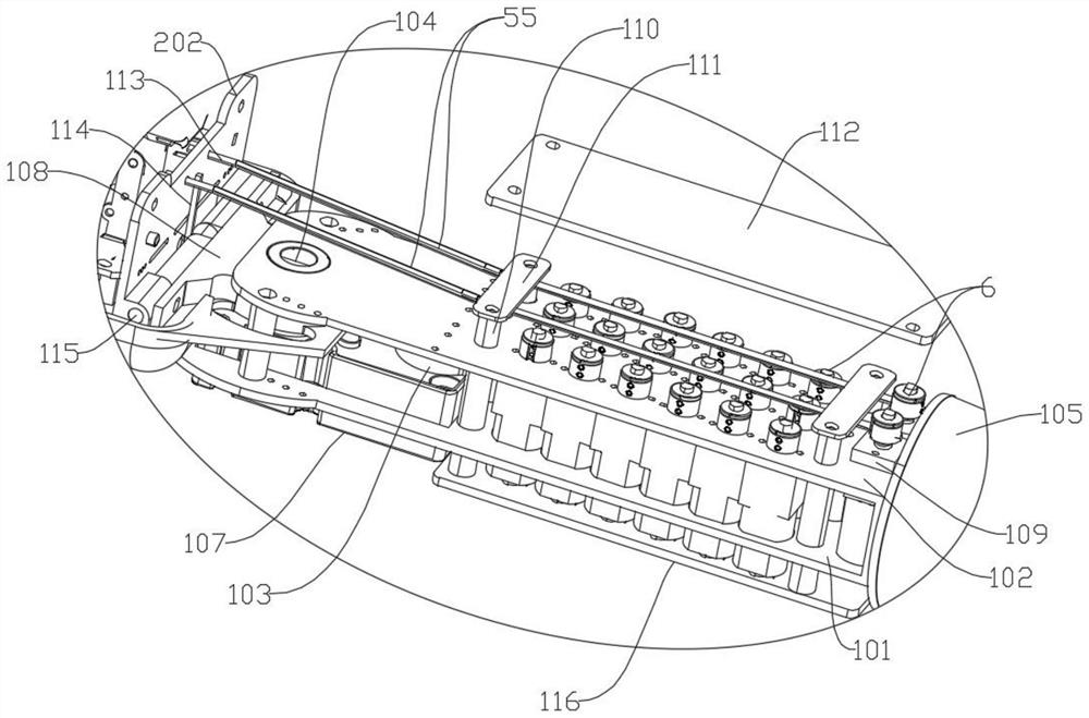
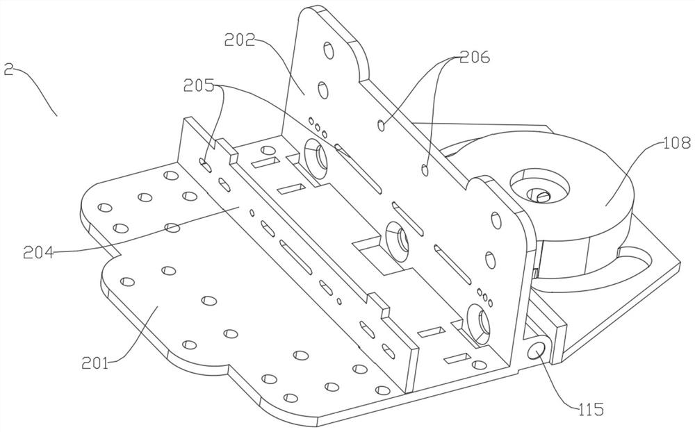
[0049] Such as figure 2 As shown, the palm 2 and the forearm 1 form the wrist left and right movement and wrist bending movement in the two directions of the cross, wherein the wrist left and right movement is formed by the rotation of the arm shaft 104, and the wrist bending movement is formed by the support ...

Embodiment 2

[0089] Such as Figure 13 and Figure 14 As shown, the difference between this embodiment and embodiment 1 is: the difference from embodiment 1 is that embodiment 1 uses 20 motors, of which 4 motors are used to control the root of 4 fingers, and the 4 motors correspond to The flexible rope is worn on the palm; in the present embodiment, at least 17 motors are used, specifically 18 motors, of which 1 motor is used to control the root of 4 fingers, and the flexible rope corresponding to the 1 motor ( Figure 14 The back flexible rope (56) in the middle is worn on the back of the hand.

[0090] The second reset member 10 in this embodiment adopts a spring; a spring is fixed between two adjacent connecting seats 301, and the root of the index finger and the root of the little finger are all provided with small holes 58 on the side of the back of the hand, and one of the motors 67 is installed on the inside of the palm board 201 ( Figure 15 shown), the back flexible rope 56 pas...

Embodiment 3

[0094] On the basis of Embodiment 2, the difference with Embodiment 2 is that the two direct motors used to control the thumb in Embodiment 2 are fixed on the forearm, while the two motors in this embodiment It is fixed on the back of the hand, which can not only reduce the load on the forearm, but also shorten the length of the forearm, and at the same time increase the strength of the thumb movement.

[0095] Such as Figure 13 , Figure 14 As shown, shown in the figure is an illustration on the basis of Embodiment 2.

[0096] As shown in the figure, 2 motors 61 are fixed on the back of the hand, and the corresponding flexible rope passes through 2 dispersing holes 205 at the base of the thumb ( Figure 11 shown), then go around the pulley 809 and be connected to the corresponding first power shaft ( Figure 9 shown in ).

[0097] In this embodiment, the two motors that control the thumb are transferred from the arm to the back of the hand, reducing the weight of the arm...


PUM


Abstract

The invention discloses a structure and a control method of a bionic robot intelligent power arm with multiple sensors, wherein the structure comprises a plurality of knuckles and a plurality of finger roots, and further comprises a power set and a traction set; the power set comprises a plurality of motors, and the traction set comprises a plurality of flexible ropes; first Hall elements and magnetic sheets are arranged on the knuckles, and the first Hall elements detect the pressure on knuckles through the magnetic sheets; the structure comprises a CPU control circuit board used for eliminating the mutual influence of the first Hall elements when the knuckles are stressed respectively; the output end and the fixed end of the motor are each provided with a magnetic ring; and the structure comprises a plurality of second Hall elements, and the second Hall elements and the magnetic rings are in one-to-one correspondence to form an encoder to control the rotation angle and the dynamic performance of the motor. Through control of the power arm, the bionic palm and the fingers have enough flexibility and grabbing force, the practical performance is improved, all the fingers are flexibly controlled, so that movement is more stable and humanoid, and the robot is specially used for a service type humanoid robot.

Description

technical field [0001] The invention relates to an anthropomorphic service robot, in particular to a structure of an intelligent power arm of a bionic robot with multiple sensors. Background technique [0002] Anthropomorphic service robots are an important field of robots. Different from industrial robots, anthropomorphic service robots generally serve individuals and families. They need to meet the requirements of completing various housework tasks and realize direct and indirect services to people. [0003] Therefore, anthropomorphic service robots generally have to adopt an anthropomorphic design as much as possible in appearance. In particular, the structural design of the hand cannot adopt the mechanical method of simple fixtures like industrial robots. It needs to be as sensitive and powerful as a human hand, and can adapt to grasp different shapes, Objects of weight, strength and softness. [0004] At present, the smart hand products on the market can be divided int...

Claims


Application Information

Patent Timeline
Patent Type & Authority Applications(China)
IPC IPC(8): B25J15/00B25J9/10B25J9/12B25J9/16
CPCB25J15/0009B25J9/104B25J9/16B25J9/12
Inventor 华宏伟
Owner 北京联合伟世科技股份有限公司
Learn More