
Movable multi-angle ejector

A multi-angle, ejector technology, used in chemical instruments and methods, waterway systems, cleaning hollow objects, etc., can solve the problems of not being able to directly wash the bottom surface of the pool, the sediment at the bottom of the pool is not clean, and the washing range is limited, etc. Achieve the effect of eliminating flushing blind spots, improving the cleaning effect, and increasing the flushing range

Pending Publication Date: 2022-02-11
SCIMEE TECH & SCI CO LTD
View PDF10 Cites 1 Cited by
  • Summary
  • Abstract
  • Description
  • Claims
  • Application Information

AI Technical Summary

Problems solved by technology

[0005] 1. The water outlet angle of the outlet pipe is constant, and the flushing distance of the parabolic water flow (that is, the distance from the outlet to the falling water point) is a certain value. Except for the farthest falling water point that can be washed, the bottom surface of the pool cannot be directly washed, and the washing range is limited. ;
[0006] 2. The maximum rotation angle can only reach 260°, and there is a dead angle (cannot radiate to the water pump), which makes it impossible to flush the range of the equipment itself and the angle that is not radiated during use, and there is a flushing blind area, resulting in sediment at the bottom of the pool not rinse well

Method used


Image

  • Movable multi-angle ejector
  • Movable multi-angle ejector
  • Movable multi-angle ejector

Examples


Embodiment Construction

[0059] In the following, only some exemplary embodiments are briefly described. As those skilled in the art would realize, the described embodiments may be modified in various different ways, all without departing from the spirit or scope of the present invention. Accordingly, the drawings and descriptions are to be regarded as illustrative in nature and not restrictive.

[0060] In describing the present invention, it should be understood that the terms "center", "longitudinal", "transverse", "upper", "lower", "front", "rear", "left", "right", " Vertical", "horizontal", "top", "bottom", "inner", "outer", "clockwise", "counterclockwise", "axial", "radial", "circumferential", etc. The orientation or positional relationship is based on the orientation or positional relationship shown in the drawings, and is only for the convenience of describing the present invention and simplifying the description, rather than indicating or implying that the referred device or element must hav...


PUM


Abstract

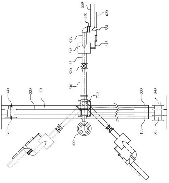
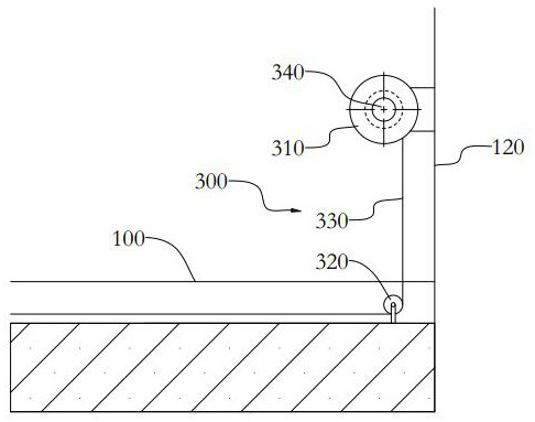
The invention provides a movable multi-angle ejector. The movable multi-angle ejector comprises a fixing support, a moving unit connected with the fixing support, a flushing water pump connected to one side of the fixing support, an ejection unit connected to the other side of the fixing support and a first swing unit installed on a water outlet pipe set of the ejection unit. The water outlet pipe set comprises a connecting elbow, a first rotating joint and a water outlet pipe which are sequentially communicated; the first swing unit comprises a water wheel and a swing rod, wherein the water wheel is rotationally arranged in a cylinder arranged in the middle of the connecting elbow; and one end of the swing rod is eccentrically connected with one end of the water wheel extending to the outside of the cylindrical cylinder, and the other end is in sliding connection with the outer side wall of the water outlet pipe. The ejection unit is driven by the moving unit to integrally move in the horizontal direction, and the flushing range of the ejection unit can be enlarged; meanwhile, the water outlet pipe is driven by the first swing unit to swing in the vertical direction, the water outlet angle can be adjusted, the water falling point can be changed to expand the flushing range, and therefore, the sediment removing effect of the storage pond is improved.

Description

technical field [0001] The invention relates to the technical field of water treatment equipment, in particular to a mobile multi-angle injector. Background technique [0002] As a rainwater collection facility, the storage tank is widely used under urban roads, buildings and other areas to store large-flow rainwater in a short period of time, and then discharge the rainwater after the flow becomes smaller, so as to ensure the smooth flow of the urban sewer system. Avoid the flood peak of large flow and play the role of regulating drainage. [0003] The storage tank is usually built underground. During the storage process, impurities in the rainwater will settle on the bottom of the tank, causing siltation at the bottom of the tank, which will affect the use of the storage tank for a long time, so it needs to be cleaned in time. [0004] The cleaning of the existing storage tanks mainly relies on manual work or the use of jet flushing devices for jet cleaning, and the jet f...

Claims


Application Information

Patent Timeline
Patent Type & Authority Applications(China)
IPC IPC(8): B08B9/093B08B13/00E03F5/10
CPCB08B9/093B08B13/00E03F5/108
Inventor 肖波王哲晓汤杰佟斯翰
Owner SCIMEE TECH & SCI CO LTD
Learn More