Moving iron loudspeaker diaphragm with small front cavity

A horn membrane and front cavity technology, which is applied to the fixing/tightening of the diaphragm, the frequency/directional characteristic device, and the sensor, etc., can solve the problems of insufficient bandwidth and difficult process of the moving iron horn, and achieve the reduction of the composite diaphragm. area, increasing the volume of the back cavity, and the effect of good bandwidth

Pending Publication Date: 2022-02-08
苏州迪倍电子科技有限公司
View PDF0 Cites 0 Cited by
  • Summary
  • Abstract
  • Description
  • Claims
  • Application Information

AI Technical Summary

Problems solved by technology

[0002] The moving iron unit moves the armature in the middle of the armature drive assembly in the magnetic field, and then drives the thimble, and then drives the diaphragm to vibrate and make sound. The front cavity of the current diaphragm diaphragm is relatively large, resulting in the bandwidth of the moving iron speaker. Insufficient, in the vertical direction, if you want to reduce the height to achieve a smaller volume, the process is very difficult

Method used


Image

  • Moving iron loudspeaker diaphragm with small front cavity
  • Moving iron loudspeaker diaphragm with small front cavity
  • Moving iron loudspeaker diaphragm with small front cavity

Examples


Embodiment 1

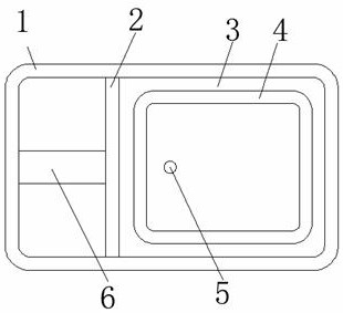
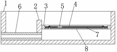
[0027] refer to Figure 1 to Figure 2 , a moving iron horn diaphragm with a small front cavity provided by the present invention: includes a casing 1, the casing 1 is composed of a front casing, a rear casing, a left casing, a right casing and a bottom casing, and the opposite side of the left casing and the right casing The distance between them is the length of the shell 1; the partition 2 is set on the inner wall of the shell 1, and the partition 2 is fixedly connected between the front shell, the rear shell and the bottom shell; it is set inside the shell 1 for frequency shifting for the formant The connecting pipe 6 for tuning, the connecting pipe 6 is fixedly connected to the upper wall of the bottom shell, and the outer walls at both ends of the connecting pipe 6 respectively penetrate the left shell of the shell 1 and the partition 2; the bracket 3 arranged inside the shell 1 is fixedly connected to the Between the partition 2 and the right shell, the inner wall of the...

Embodiment 2

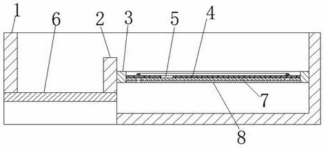
[0031] refer to image 3 , a moving iron horn diaphragm with a small front cavity provided by the present invention: the connecting pipe 6 is installed in a semicircular tube, and the center of the circle is on the same plane as the lower wall of the bottom case, thus a double moving iron unit can be derived, and each unit is semicircular The tubes are relatively composed of a whole tube, and more tuning methods have been obtained.

[0032] Working principle: The composite diaphragm vibrates through the drive part inside the moving iron unit to generate sound. By setting the partition 2 inside the shell 1, the volume of the front cavity is smaller, and the area of ​​the composite diaphragm is reduced, so that more sound can be obtained. Good bandwidth, while increasing the volume of the back cavity, so that higher sound pressure can be obtained. The performance of the product can be adjusted by replacing the connecting tube 6 with different inner diameters, different materials...


PUM


Abstract

The invention discloses a moving iron loudspeaker diaphragm with a small front cavity, and the diaphragm comprises a shell, wherein the shell is composed of a front shell, a rear shell, a left shell, a right shell and a bottom shell, and the distance between the opposite sides of the left shell and the right shell is equal to the length of the shell; and a partition plate which is arranged on the inner side wall of the outer shell and fixedly connected among the front shell, the rear shell and the bottom shell. According to the invention, the partition plate is arranged in the shell, so that the size of the front cavity is smaller, the area of the composite diaphragm is reduced, better bandwidth can be obtained, the size of the rear cavity is increased, higher sound pressure can be obtained, and the front cavity is connected with the outside of the shell through the connecting pipe, so the performance of the product can be adjusted by selecting the connecting pipes with different inner diameters, different materials and different shapes; frequency shift is carried out aiming at the formant of the product so as to help a customer to carry out better tuning, and the condition that the product is difficult to generate the formant with lower frequency under the condition of smaller volume is also overcome.

Description

technical field [0001] The invention relates to the technical field of moving iron horns, in particular to a diaphragm of a moving iron horn with a small front chamber. Background technique [0002] The moving iron unit moves the armature in the middle of the armature drive assembly in the magnetic field, and then drives the thimble, and then drives the diaphragm to vibrate and make sound. The front cavity of the current diaphragm diaphragm is relatively large, resulting in the bandwidth of the moving iron speaker. Insufficient, in the vertical direction, it is very difficult to reduce the height to achieve a smaller volume. Contents of the invention [0003] The purpose of the present invention is to solve the shortcomings in the prior art, and propose a moving iron horn diaphragm with a small front chamber. [0004] In order to achieve the above object, the present invention adopts the following technical solution: a moving iron horn diaphragm with a small front cavity,...

Claims


Application Information

Patent Timeline
Patent Type & Authority Applications(China)
IPC IPC(8): H04R1/28H04R7/16H04R11/02
CPCH04R1/2811H04R7/16H04R11/02
Inventor 孟献振
Owner 苏州迪倍电子科技有限公司
Why Eureka
Try Eureka