
Method for measuring direct current magnetic bias current of neutral point multi-point grounding power transformer

A technology for power transformers and DC bias magnetization, which is applied in transformer testing, measuring devices, and only measuring current, etc. It can solve problems such as distortion of measurement results, and achieve the effects of simple installation, increased implementation difficulty, and easy installation.

Pending Publication Date: 2022-02-08
STATE GRID HUBEI ELECTRIC POWER RES INST +1
View PDF1 Cites 1 Cited by
  • Summary
  • Abstract
  • Description
  • Claims
  • Application Information

AI Technical Summary

Problems solved by technology

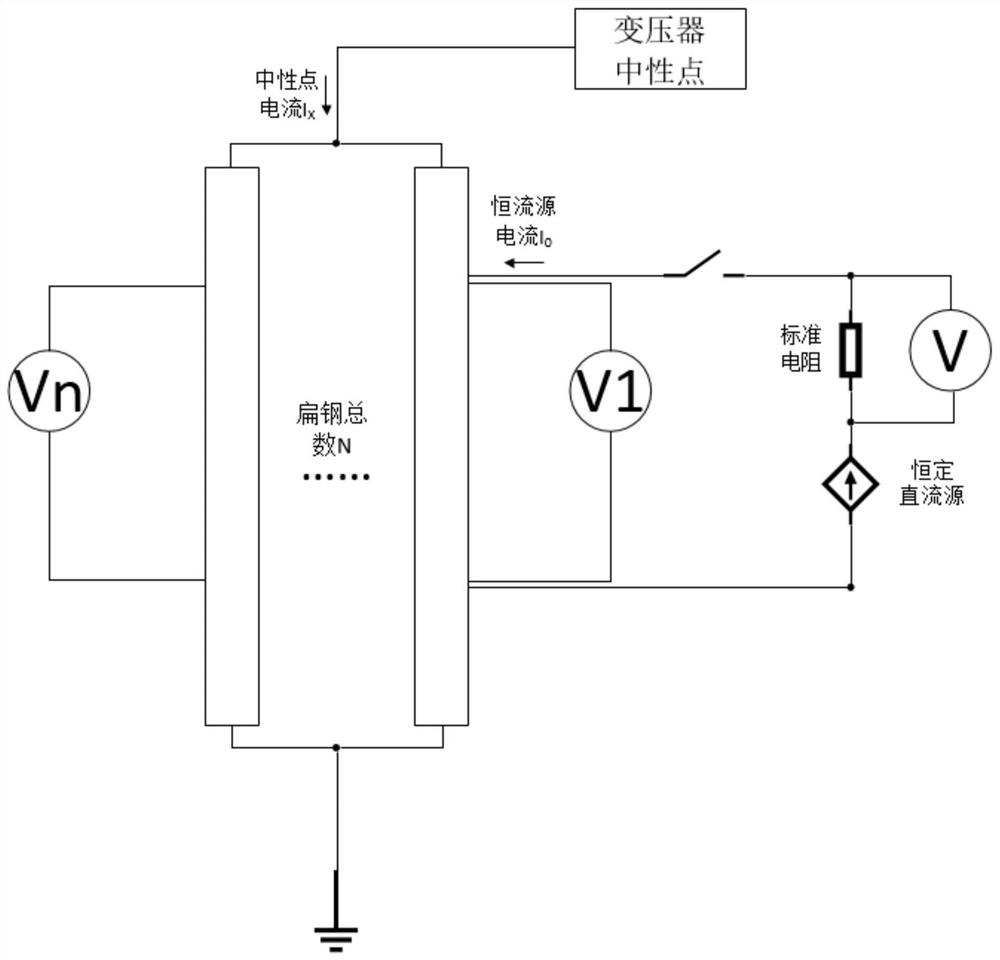
[0005] Aiming at the problem that the neutral points of power transformers in substations and power plants are connected to the ground at multiple points, and the measurement results of the traditional resistance sampling DC bias current measurement method are distorted, the present invention proposes a method suitable for multiple points of neutral points connected to the ground (such as double-grounded flat Steel, four-ground flat steel and other multi-input locations) DC bias current measurement method for power transformers

Method used


Image

  • Method for measuring direct current magnetic bias current of neutral point multi-point grounding power transformer
  • Method for measuring direct current magnetic bias current of neutral point multi-point grounding power transformer
  • Method for measuring direct current magnetic bias current of neutral point multi-point grounding power transformer

Examples


Embodiment Construction

[0033] In order to make the purpose, technical solutions and advantages of the embodiments of the present invention clearer, the technical solutions in the embodiments of the present invention will be clearly and completely described below in conjunction with the drawings in the embodiments of the present invention. Obviously, the described embodiments It is a part of embodiments of the present invention, but not all embodiments. Based on the embodiments of the present invention, all other embodiments obtained by persons of ordinary skill in the art without making creative efforts belong to the protection scope of the present invention.

[0034] For the same substation, it is impossible to directly change the number of neutral point grounding flat steel, and installing a resistor between the flat steel and the support pole will change the grounding method of the neutral point. In order to avoid the above situation, the embodiment of the present invention directly intercepts the...


PUM

PropertyMeasurementUnit
Lengthaaaaaaaaaa

Abstract

The invention provides a method for measuring the direct current magnetic bias current of a neutral point multi-point grounding power transformer, which comprises the following steps of: 1, cutting sampling flat steel with the same length from each grounding flat steel as a sampling resistor, and applying a current source to two ends of one of the sampling flat steel; 2, connecting voltmeters to two ends of the cut length of each sampling flat steel, and sampling voltage signals of the sampling flat steel; and 3, enabling the current source to apply currents of different magnitudes twice, enabling each piece of sampling flat steel to respectively extract voltage signals under the working condition of the currents twice, obtaining the actual resistance value of the sampling resistor through conversion under the condition of considering the inherent grounding current of the neutral point through the known current and voltage signals, and then measuring a direct-current magnetic bias current signal flowing through each piece of flat steel. The method can accurately measure the direct-current magnetic bias current of the neutral point of the power transformer when multiple grounding flat steel is grounded, is suitable for field detection and on-line monitoring, and has the advantages of being free of temperature drift and capable of being calibrated on line compared with a traditional Hall sensor.

Description

technical field [0001] The invention relates to the technical field of electrical parameter measurement in a power system, in particular to a method for measuring DC bias current of a neutral-point multi-point-to-ground power transformer. Background technique [0002] When the DC transmission system operates under the unbalanced condition of single pole or bipolar pole, the DC current is injected into the ground through the DC grounding pole, and the AC transmission system forms a parallel circuit with the ground through the neutral point of the grounded transformer, the transmission line and the ground wire of the overhead line. Shunt the DC current into the ground, and the shunt size can reach tens of amperes. This phenomenon is called DC bias phenomenon, which will distort the excitation current of the transformer, saturate the iron core, and affect the magnetostrictive properties of the iron core silicon steel sheet, resulting in The vibration and noise of the transforme...

Claims


Application Information

Patent Timeline
IPC IPC(8): G01R19/00G01R31/62
CPCG01R19/0092G01R31/62
Inventor 吴传奇李晓辉阮羚全江涛卢军陈理李红兵李小双黄霍刘海娟童歆束龙孟毅文雅钦陈堃夏天李劲彬王亮
Owner STATE GRID HUBEI ELECTRIC POWER RES INST
Learn More