
Device for binding stirrups at beam-column joint of frame structure

A frame structure and frame column technology, applied in the direction of structural elements, building components, building structures, etc., can solve the problems of low construction efficiency, affecting the overall bearing capacity, time-consuming and labor-intensive problems, so as to improve construction efficiency, realize stable fixation, overcome effect of shortage

Pending Publication Date: 2022-02-08
DATONG TAIRUI GRP CONSTR +1
View PDF0 Cites 0 Cited by
  • Summary
  • Abstract
  • Description
  • Claims
  • Application Information

AI Technical Summary

Problems solved by technology

[0003] In order to solve the problems of time-consuming and labor-intensive binding of steel bars in the existing frame structure, low construction efficiency and affecting the overall bearing capacity, the present invention provides a stirrup binding device at the beam-column junction of the frame structure

Method used


Image

  • Device for binding stirrups at beam-column joint of frame structure
  • Device for binding stirrups at beam-column joint of frame structure
  • Device for binding stirrups at beam-column joint of frame structure

Examples


Embodiment Construction

[0017] It should be noted that, in the case of no conflict, the embodiments in the present application and the features in the embodiments can be combined with each other. The present invention will be described in detail below with reference to the accompanying drawings and examples.

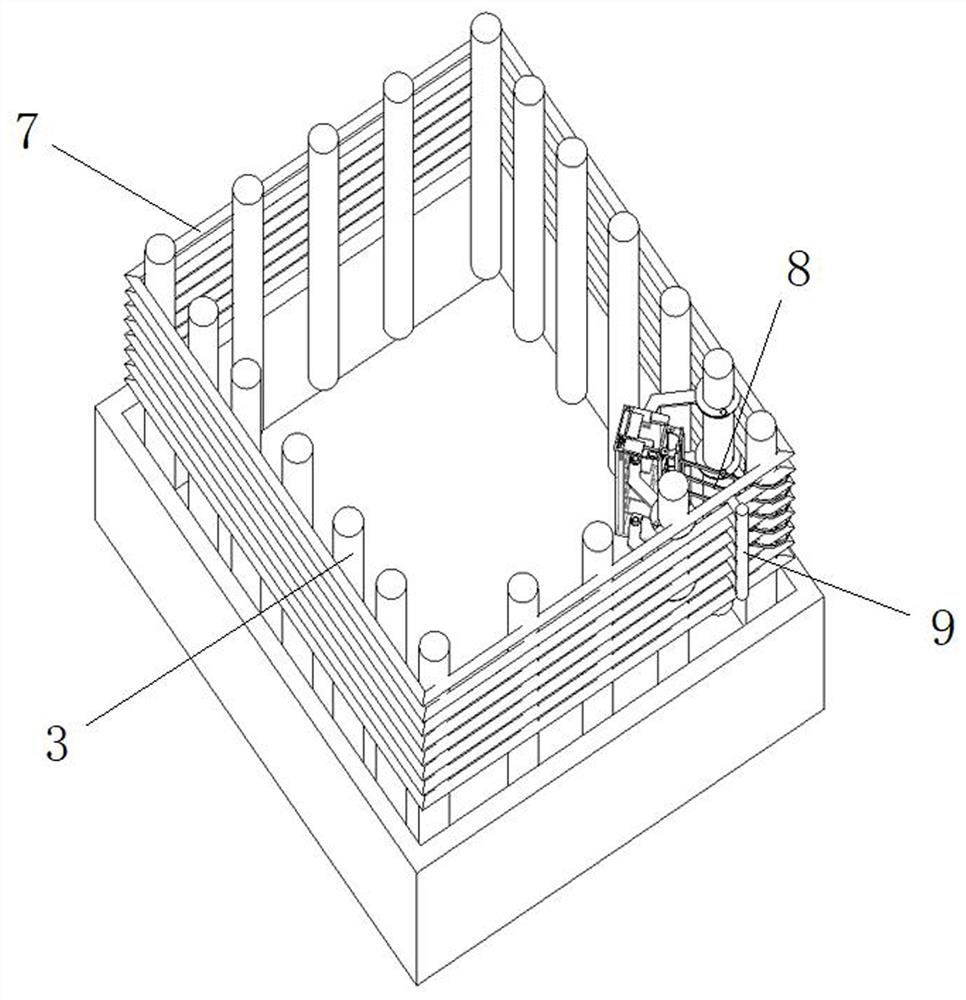
[0018] like Figure 1-4 As shown, according to one embodiment of the present invention, a device for binding stirrups at the junction of beams and columns of a frame structure is provided. It includes a vertically arranged frame column formwork 1, the upper end of the frame column formwork 1 is provided with a frame beam formwork 2 connected to it and crossed, the frame column formwork 1 is provided with a vertically placed frame column main reinforcement 3, and the frame column main reinforcement 3 The frame column stirrup 4 is fixed on the outer edge, and the frame beam formwork 2 is provided with the frame beam main reinforcement 5 placed horizontally, the frame beam stirrup 6 is fixed on t...


PUM


Abstract

The invention particularly relates to a device for binding stirrups at the beam-column joint of a frame structure, and solves the problems that time and labor are wasted, the construction efficiency is low and the overall bearing capacity is affected when reinforcing steel bars of an existing frame structure are bound. Beam column stirrups are arranged on the outer edges of the frame column main reinforcements, plastic ribbons are connected to the staggered positions of the beam column stirrups and the frame column main reinforcements at the corners of the beam column stirrups, interval positioning reinforcements are arranged on the outer sides of the four corners of the beam column stirrups, and ribbon binding mechanisms are arranged on the inner sides of the four corners of the beam column stirrups. Each ribbon binding mechanism comprises a hollow square tube, a lifting plate is arranged in the hollow square tube, an occlusion mechanism is arranged on the lifting plate, a ribbon hole is formed in the front side wall of the hollow square tube, and heating plates are arranged on the left side and the right side of the ribbon hole. Rapid binding of the frame column main reinforcements and the beam column stirrups at the outer edges corresponding to the frame column main reinforcements is completed, the problems of shortage and binding missing of the beam column stirrups are solved, meanwhile, the construction efficiency is improved, and the overall bearing capacity of a frame structure is guaranteed.

Description

technical field [0001] The invention relates to an auxiliary device for binding a frame structure, in particular to a stirrup binding device at the intersection of beams and columns of a frame structure. Background technique [0002] In the construction of frame structure reinforcement, it is necessary to carry out the binding of stirrups. Due to the dense reinforcement at the junction of frame beams and columns, it is difficult for workers to operate during the binding process, which is time-consuming and laborious, which seriously affects the construction efficiency. The phenomenon of missing binding affects the overall bearing capacity of the frame structure. Contents of the invention [0003] In order to solve the problems of time-consuming and labor-intensive binding of steel bars in the existing frame structure, low construction efficiency and influence on the overall bearing capacity, the invention provides a stirrup binding device at the beam-column junction of the...

Claims


Application Information

Patent Timeline
Patent Type & Authority Applications(China)
IPC IPC(8): E04G21/12E04C5/06
CPCE04G21/123E04C5/0609
Inventor 任旭红刘广付子光高志伟刘鑫张宝张国栋赵向峰李向东白天主刘云龙胡艳花王江张强尉鹏
Owner DATONG TAIRUI GRP CONSTR
Learn More