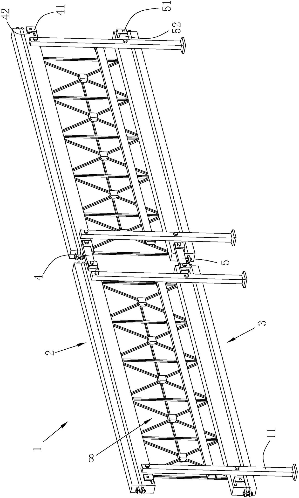
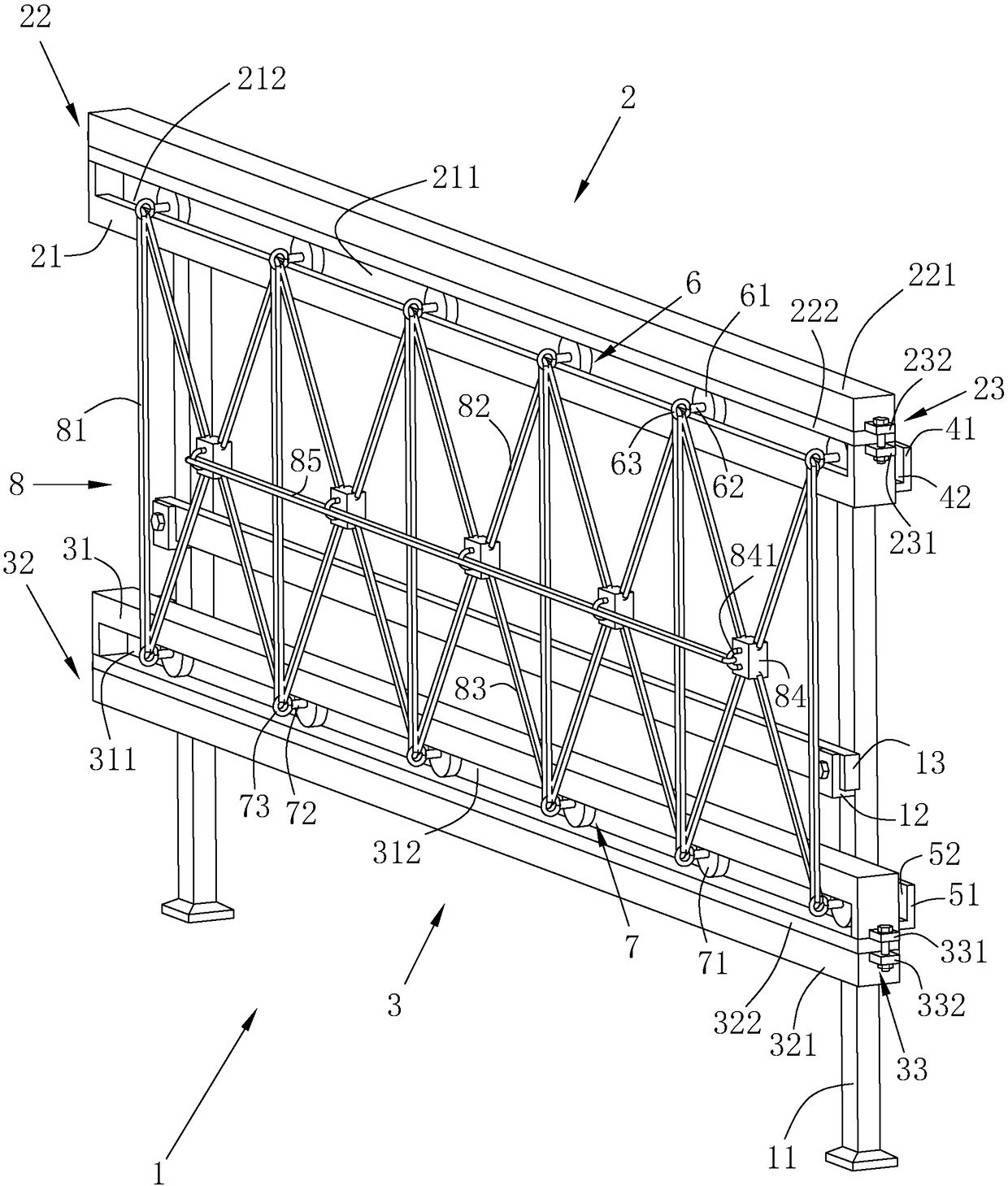
Prefabricated guardrail
A prefabricated guardrail technology, which is applied in the direction of fences, road safety devices, roads, etc., can solve the problems of inconvenient transportation and storage, complex disassembly and reassembly process, large footprint of guardrail units, etc., and achieve the effect of convenient operation
- Summary
- Abstract
- Description
- Claims
- Application Information
AI Technical Summary
Problems solved by technology
Method used
Image
Examples
Embodiment 2
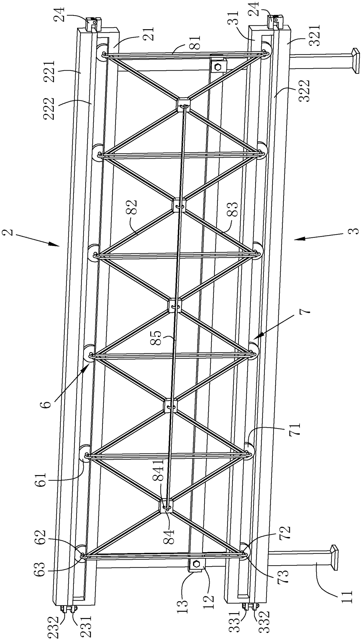
[0070] The difference from Example 1 is that, referring to figure 2 , the horizontal heights of all connecting plates 84 are consistent, connecting rings 841 are fixed on the connecting plates 84, and the flexible net 8 also includes a horizontal stay rope 85 that runs through all connecting rings 841 and connects end to end. When the two auxiliary sliders 7 located at both ends of the length direction of the main railing 2 and with the largest spacing are located at both ends of the length direction of the auxiliary railing 3 , the horizontal stay rope 85 is in a tight state.
[0071]The mesh opening of the flexible net 8 is further reduced by the horizontal pull rope 85 to better prevent people from falling, and at the same time, the local force of the flexible net 8 is distributed to the entire flexible net 8 by the taut horizontal pull rope 85 to avoid local stress The flexible net 8 is damaged, and the stability of the flexible net 8 is improved.
Embodiment 3
[0073] The difference with embodiment 2 is that, referring to figure 2 The support column 11 is detachably connected with a connecting railing 13, and the support column 11 is fixed with a fixed block 12 between the main railing 2 and the auxiliary railing 3. The fixed block 12 is located on the side of the support column 11 facing the construction site. The fixed block 12 There is a fixed groove downwardly recessed along the vertical direction, and the two ends of the fixed groove are connected with the outside along the length direction of the main railing 2. The connecting railing 13 is clamped in the fixing groove, and passes through the fixing block 12 and the connecting railing 13 through threaded fasteners. And abut on the support column 11 so that the support column 11 is connected with the connecting railing 13, the connecting railing 13 is located on the side of the flexible net 8 away from the construction site, the height of the connecting railing 13 is located bet...
Embodiment 4
[0076] The difference with embodiment 3 is that, referring to figure 2 , the main locking rod 221 is a rectangular rod, and the main locking rod 221 is provided with a main friction layer 222 on one side facing the main slider 6. In this embodiment, the main friction layer 222 is made of rubber. In other embodiments, polyurethane, Plastic etc.
[0077] The auxiliary locking rod 321 is a rectangular rod, and the side of the auxiliary locking rod 321 facing the auxiliary sliding part 7 is provided with an auxiliary friction layer 322. In this embodiment, the auxiliary friction layer 322 is made of rubber. In other embodiments, polyurethane, plastic, etc. can be used. Wait.
[0078] The main friction layer 222 increases the coefficient of friction of the side of the main locking rod 221 facing the main sliding part 6, so that the frictional force increases when the main locking rod 221 is pressed against the top of the main sliding part 6, and the locking of the main sliding pa...
PUM
 Abstract
Description
Claims
Application Information
 - R&D
- Intellectual Property
- Life Sciences
- Materials
- Tech Scout
- Unparalleled Data Quality
- Higher Quality Content
- 60% Fewer Hallucinations
Browse by: Latest US Patents, China's latest patents, Technical Efficacy Thesaurus, Application Domain, Technology Topic, Popular Technical Reports.
© 2025 PatSnap. All rights reserved.Legal|Privacy policy|Modern Slavery Act Transparency Statement|Sitemap|About US| Contact US: help@patsnap.com


