Special-shaped blade contact type rotation control rotating movable wing device

A contact type, blade technology, applied in aircraft control, motor vehicle, transportation and packaging, etc., to achieve the effect of low production cost, simple structure and good reliability

Pending Publication Date: 2022-02-08
GLOBAL INST OF SOFTWARE TECH
View PDF0 Cites 0 Cited by
  • Summary
  • Abstract
  • Description
  • Claims
  • Application Information

AI Technical Summary

Problems solved by technology

[0005] The purpose of the present invention is to provide a very significant reduction in flight resistance of aircraft, improve aerodynamic efficiency, provide lift and thrust at the same time, different from the special-shaped blade contact rotation control of rotor flight and flapping wing flight, to Solve the above-mentioned problems existing in the existing flapping wing and rotor technology

Method used


Image

  • Special-shaped blade contact type rotation control rotating movable wing device
  • Special-shaped blade contact type rotation control rotating movable wing device
  • Special-shaped blade contact type rotation control rotating movable wing device

Examples


Embodiment 1

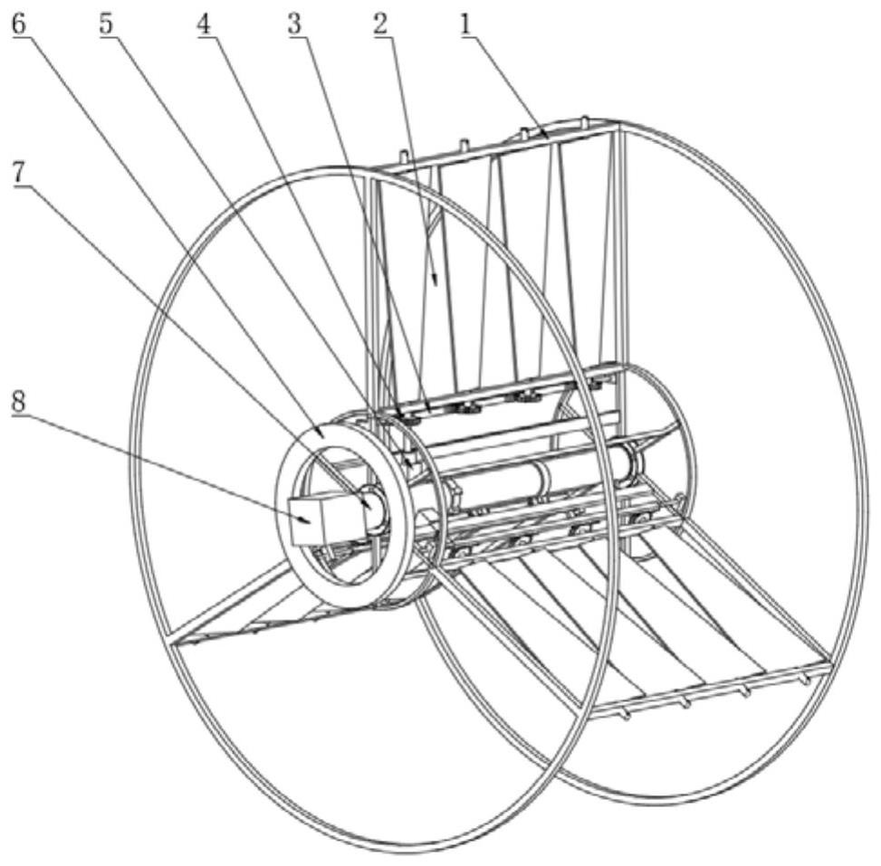
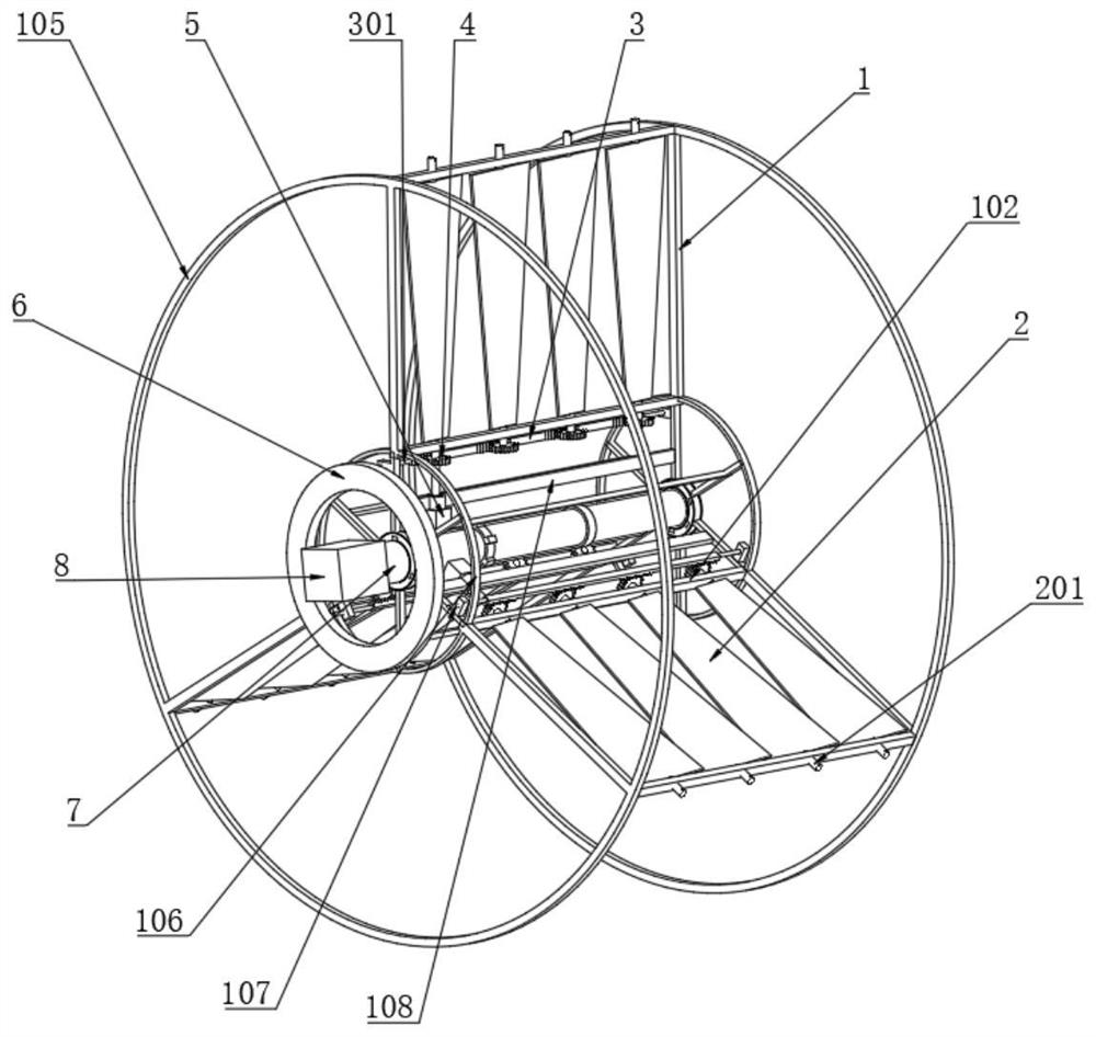
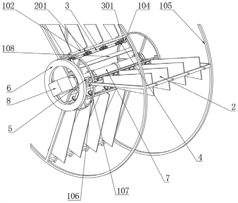
[0039] to combine figure 1 , figure 2 , image 3 , Figure 4 , Figure 5 , Image 6 , Figure 7 , Figure 8 , Figure 9 and Figure 10 , a high-voltage wire inspection UAV with a rotating wing device controlled by special-shaped blade contact rotation, including a rotating wing, a transmission mechanism, a servo motor 5, a conductive disc 6, a rotating shaft 7 and a motor 8, and the rotating wing is fixed Connected to the rotating shaft 7, the motor 8 arranged on the aircraft is connected to the rotating shaft 7, and makes the rotating shaft 7 rotate continuously; the rotating rotor includes a rotating frame 1, and rotatable special-shaped blades 2 installed in the rotating frame 1, The shape function of special-shaped blade 2 is determined by the following piecewise function: formula Ⅰ:

[0040]

[0041] Formula II:

[0042] In the formula:

[0043] a——the length coefficient of the blade in the piecewise function;

[0044] L——the length of the special-shaped b...


PUM


Abstract

The invention relates to a special-shaped blade contact type rotation control rotating movable wing device of an unmanned aerial vehicle. The device includes a rotating movable wing, a transmission mechanism, a servo motor, a conductive disc, a rotating shaft and a motor, wherein the rotating movable wing is fixedly connected to the rotating shaft, the motor arranged on the aircraft is connected with the rotating shaft and enables the rotating shaft to rotate, and the rotating movable wing comprises a rotating frame and a rotatable special-shaped blade installed in the rotating frame; and the servo motor, the conductive disc and the transmission mechanism are used for controlling rotation and resetting of the special-shaped blades. The advantages of flapping wing flight and rotor wing flight are absorbed, and the defects of the flapping wing flight and the rotor wing flight are overcome. The device can solve the bottleneck problem of low aerodynamic efficiency in the current small and micro aircrafts, and has the characteristics of small standby stroke resistance, large and stable working stroke thrust, high aerodynamic efficiency, simple structure and convenience in manufacturing. The device can be widely applied to various small aircrafts and unmanned aerial vehicles with low Reynolds number flight.

Description

technical field [0001] The invention relates to the field of movable wing aircraft and flying robots, in particular to a rotary movable wing device for contact-type autorotation control of special-shaped blades of unmanned aerial vehicles. Background technique [0002] There are three flight types of aircraft: fixed wing, rotary wing and flapping wing, both of which are movable wings. Flapping wing flight is a flying method adopted by flying creatures in nature. It mainly uses the up and down flapping of the wings to generate lift and thrust at the same time. Flexibility, more suitable for performing flights around obstacles etc. For small-sized and low-speed flying aircraft, flying at low Reynolds numbers, the unsteady lift generated by the flapping wing is much greater than the constant lift of the fixed wing; [0003] In terms of thrust, flapping wing propulsion is more efficient than propeller propulsion. At present, the research of flapping-wing aircraft mainly focus...

Claims


Application Information

Patent Timeline
IPC IPC(8): B64C39/00B64C21/08
CPCB64C39/003B64C21/08
Inventor 夏青元惠越超周雪峰胡诚朱佾孙宇珊丁荣晖邱明廖振强
Owner GLOBAL INST OF SOFTWARE TECH
Why Eureka
Try Eureka