
Inspection robot

A technology for inspection robots and casings, applied in the field of inspection robots, can solve problems such as time-consuming, difficult for tunnel managers, and difficult to be understood, so as to improve comprehensiveness and accuracy, avoid mutual influence, and improve movement ability Effect

Active Publication Date: 2022-02-08
UNIV OF SCI & TECH OF CHINA
View PDF10 Cites 2 Cited by
  • Summary
  • Abstract
  • Description
  • Claims
  • Application Information

AI Technical Summary

Problems solved by technology

At present, the operation inspection and maintenance of tunnels are mainly manual. There are problems such as time-consuming, low efficiency, easy to miss inspection, and the accuracy of inspection results is limited by the observation of daily maintenance personnel and the timeliness of instrument inspection, which makes tunnel managers difficult. Quickly make accurate judgments
In addition, in recent years, accidents such as tunnel fires, explosions, and collapses have occurred in many places. Before and after the accidents, the internal environment is relatively complex and difficult to understand, making rescue difficult. Advanced advantages help us understand the specific circumstances of the accident, but the current inspection robot also has some shortcomings:
[0003] (1) Among the currently known inspection robots, there are vacancies in the types of pre-disaster, during-disaster and post-disaster inspection, detection and judgment for sudden accidents such as fires, explosions, and collapses in tunnels and underground spaces;
[0004] (2) Existing inspection robots lack high temperature resistance and impact resistance, and cannot fully adapt to complex environments such as tunnels and subway tracks, such as fires, high temperatures during collapses, stone impacts, and impacts;
[0005] (3) The existing inspection robot has the disadvantage of slow movement speed

Method used


Image

  • Inspection robot
  • Inspection robot
  • Inspection robot

Examples


Embodiment Construction

[0038] In order to make the object, technical solution and advantages of the present invention clearer, the present invention will be further described in detail below in conjunction with the accompanying drawings and embodiments. It should be understood that the specific embodiments described here are only used to explain the present invention, and are not intended to limit the present invention.

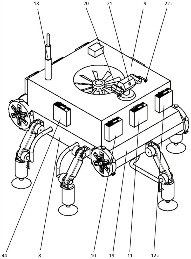
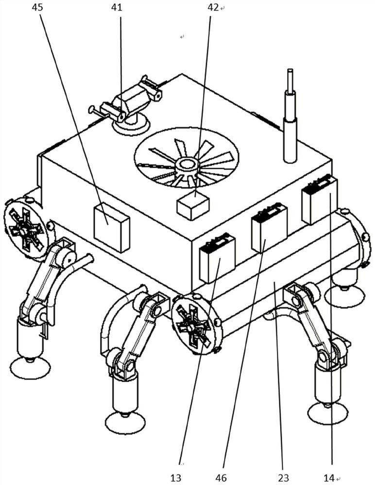
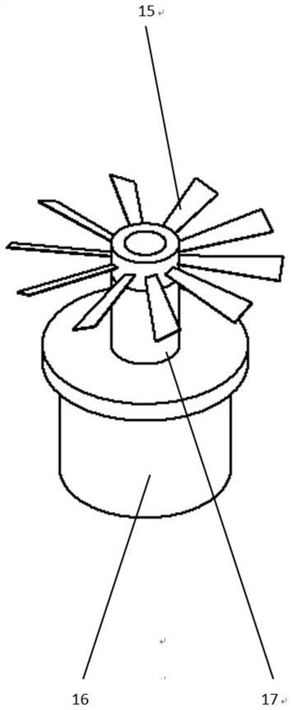
[0039] An inspection robot, which includes an attachment mechanism, a detection structure, a motion mechanism, a radio communication mechanism, an evacuation mechanism, a heat dissipation mechanism and a fuselage structure; as figure 1 , figure 2 As shown, the fuselage mechanism includes an upper casing (8), a lower casing (9), a front side plate (19), and a rear side plate (23), wherein the lower casing (8), the upper casing (9) It is the base frame for the inspection robot to install other parts. The infrared temperature sensor (10), laser ranging sensor (11), smoke sensor (12)...


PUM


Abstract

The invention discloses an inspection robot which comprises an attachment mechanism, a detection structure, a movement mechanism, a radio communication mechanism, an evacuation mechanism, a heat dissipation mechanism and a machine body structure. The inspection robot is mainly provided for tunnels, subway rail environments, pipe galleries, high-rise buildings and village and town buildings, can avoid interference on normal operation of ground vehicles, has the rapid detection capacity and is high in movement speed, daily inspection can be conducted, workers can be matched for tunnel maintenance, and before and after accidents happen, detection of sudden accidents and disasters is carried out. The effect that the inspection robot is attached to the wall surface to move can be achieved, the main purposes of improving the movement speed of the inspection robot, changing the movement form of a traditional inspection robot and avoiding interference of the inspection robot to normal operation of traffic flow in the inspection work are achieved, and the method has great significance in improving the inspection capacity of the inspection robot.

Description

technical field [0001] The invention relates to the technical field of robots, in particular to an inspection robot, which is used for inspection of accidents in tunnels, underground spaces and buildings. Background technique [0002] With the increase of highway tunnel mileage and traffic flow, the types of tunnel equipment and facilities are gradually increasing, which brings greater pressure on the daily maintenance and management of tunnels. At present, the operation inspection and maintenance of tunnels are mainly manual, and there are problems such as time-consuming, low efficiency, easy to miss inspection, and the accuracy of inspection results is limited by the observation of daily maintenance personnel and the timeliness of instrument inspection, which makes tunnel managers difficult. Quickly make accurate judgments. In addition, in recent years, accidents such as tunnel fires, explosions, and collapses have occurred in many places. Before and after the accidents, ...

Claims


Application Information

Patent Timeline
Patent Type & Authority Applications(China)
IPC IPC(8): B62D57/024E21F17/18
CPCB62D57/024E21F17/18
Inventor 唐飞刘紫玮黄亚军梁建文胡隆华张晓磊
Owner UNIV OF SCI & TECH OF CHINA
Learn More