Tire degradation estimating device, and tire degradation estimating method
An inference device, tire technology, applied in the direction of tire tread/tread pattern, tire measurement, tire parts, etc., can solve the problems of erroneous wear status evaluation, cumbersome inspection work, etc., and achieve the effect of high accuracy of calculation amount
- Summary
- Abstract
- Description
- Claims
- Application Information
AI Technical Summary
Problems solved by technology
Method used
Image


Examples
no. 1 approach
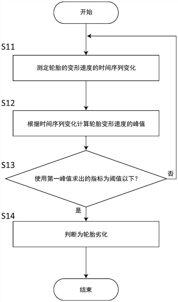
[0046] Such as figure 1 As shown, the tire deterioration estimation method of this embodiment is a tire deterioration estimation method using a tire deterioration estimation device disposed on the inner surface of the tire, and includes a deformation speed measurement step (S11), a calculation step (S12), and an estimation step (S13 ). Each step will be described below.
[0047] The deformation speed measurement step ( S11 ) is a step of measuring the deformation speed of a portion of the rotating tire 200 where the tire deterioration estimation device 100 is disposed, that is, the tire deformation speed. figure 2 (a) is a front view schematically showing deformation when the tire 200 is rotating, figure 2 (b) is a waveform schematically showing time-series changes in the tire deformation speed and tire deformation amount measured by the tire deterioration estimation device 100 in the rotating tire 200 . In the figure, the solid line indicates the time-series change of th...
no. 2 approach
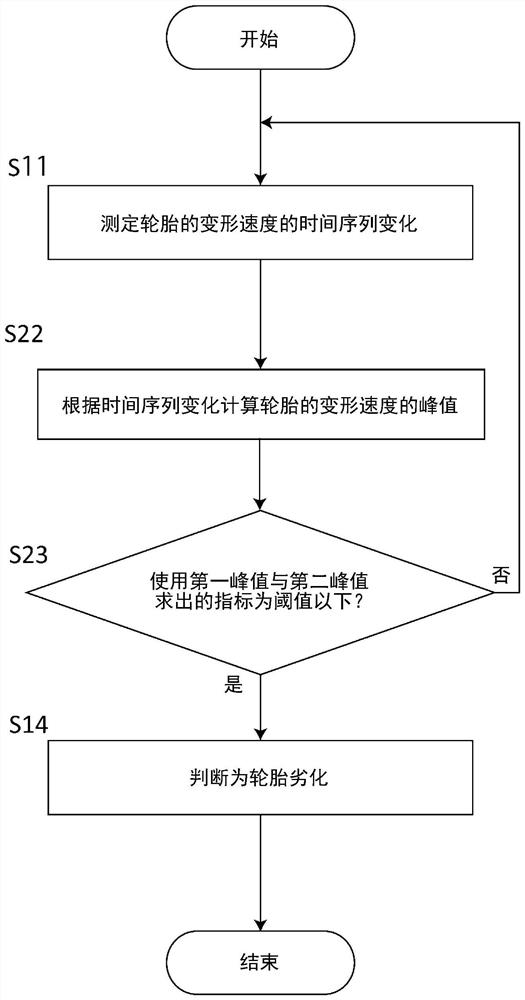
[0056] Such as image 3 As shown, the tire deterioration estimation method of this embodiment differs from the first embodiment in that a calculation step ( S22 ) is provided instead of the above-mentioned calculation step ( S12 ). The calculation step ( S22 ) calculates a second peak value of the tire deformation speed when the tire touches the ground in addition to the first peak value.
[0057] The second peak is the peak with the largest peaks on the top side and the bottom side. In the calculation step (S22), the second peak value is calculated in addition to the first peak value, so that the first peak value and the second peak value can be used in the estimation step (S23). Accordingly, in estimating the degree of deterioration of the tire, it is possible to take into account the influence of the change in the characteristics of the tire due to an external temperature change or the like, and thus the estimation accuracy can be improved.
[0058] Such as figure 2 As ...
no. 3 approach >
[0063] The method of estimating the degree of deterioration of the tire in this embodiment replaces the time-series change of the deformation speed of the tire ( figure 2 The solid line of (b)), using the time series change according to the deformation of the tire ( figure 2 The third peak value of the tire deformation determined by the dotted line in (b), infers the degree of deterioration of the tire.
[0064] Such as Figure 4 As shown, the method for estimating the degree of deterioration of a tire according to this embodiment includes a deformation amount measuring step ( S31 ), a calculating step ( S32 ), and an estimating step ( S33 ).
[0065] The deformation amount measuring step ( S31 ) is a step of measuring the time-series change of the tire deformation amount, for example, measuring the tire deformation speed while the tire is rotating, and integrating the tire deformation speed to measure the tire deformation amount. Thereby, a waveform of a time-series chang...
PUM
 Abstract
Description
Claims
Application Information
 - R&D
- Intellectual Property
- Life Sciences
- Materials
- Tech Scout
- Unparalleled Data Quality
- Higher Quality Content
- 60% Fewer Hallucinations
Browse by: Latest US Patents, China's latest patents, Technical Efficacy Thesaurus, Application Domain, Technology Topic, Popular Technical Reports.
© 2025 PatSnap. All rights reserved.Legal|Privacy policy|Modern Slavery Act Transparency Statement|Sitemap|About US| Contact US: help@patsnap.com