Fisheye lens
A fisheye lens and lens technology, applied in the field of imaging lens, can solve the problem that it is difficult to meet the diversified use requirements of drones, and achieve the effects of reasonable setting, strong thermal stability, and reduced volume and weight
- Summary
- Abstract
- Description
- Claims
- Application Information
AI Technical Summary
Problems solved by technology
Method used
Image


Examples
Embodiment 1
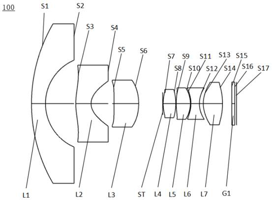
[0119] see figure 1 , which is a schematic structural diagram of the fisheye lens 100 provided in Embodiment 1 of the present invention, the fisheye lens includes in sequence from the object side to the imaging surface along the optical axis: a first lens L1, a second lens L2, a third lens L3, The optical centers of the diaphragm ST, the fourth lens L4, the fifth lens L5, the sixth lens L6, the seventh lens L7, and the filter G1 are located on the same straight line.
[0120] The first lens L1 has negative refractive power, the object side S1 of the first lens is a convex surface, and the image side S2 of the first lens is a concave surface;
[0121] The second lens L2 has a negative refractive power, the object side S3 of the second lens is a convex surface, and the image side S4 of the second lens is a concave surface;
[0122] The third lens L3 has positive refractive power, the object side S5 of the third lens is a convex surface at the near optical axis, and the image si...
Embodiment 2
[0139] see Figure 5 , which is a schematic structural view of the fisheye lens 200 provided in Embodiment 2 of the present invention. The fisheye lens 200 in this embodiment is roughly the same as the fisheye lens 100 in Embodiment 1. The reason is that there are differences in the radius of curvature and thickness of each lens and the air space between each lens.
[0140] The relevant parameters of each lens of the fisheye lens 200 provided in this embodiment are shown in Table 2-1.
[0141] table 2-1
[0142]
[0143] The relevant parameters of the aspheric lens of the fisheye lens 200 in this embodiment are shown in Table 2-2.
[0144] Table 2-2
[0145]
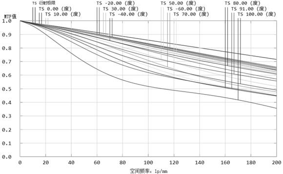
[0146] In this embodiment, the MTF curve, the F-Theta distortion curve, and the axial chromatic aberration curve of the fisheye lens 200 are as follows: Image 6 , Figure 7 and Figure 8 shown.
[0147] see Image 6 , shows the MTF curve diagram of the fisheye lens in this embodiment, the horizontal axis r...
Embodiment 3
[0151] see Figure 9 , which is a schematic structural diagram of the fisheye lens 300 provided in Embodiment 3 of the present invention. The surface unevenness of each lens of the fisheye lens 300 in this embodiment and the fisheye lens 100 in Embodiment 1 is roughly the same, and the difference is The reason is that there are differences in the radius of curvature and thickness of each lens and the air space between each lens.
[0152] The relevant parameters of each lens of the fisheye lens 300 provided in this embodiment are shown in Table 3-1.
[0153] Table 3-1
[0154]
[0155] The relevant parameters of the aspheric lens of the fisheye lens 300 in this embodiment are shown in Table 3-2.
[0156] Table 3-2
[0157]
[0158] In this embodiment, the MTF curve diagram, the F-Theta distortion curve diagram, and the axial chromatic aberration curve diagram of the fisheye lens 300 are respectively as follows Figure 10 , Figure 11 and Figure 12 shown.
[0159] ...
PUM
 Abstract
Description
Claims
Application Information
 - Generate Ideas
- Intellectual Property
- Life Sciences
- Materials
- Tech Scout
- Unparalleled Data Quality
- Higher Quality Content
- 60% Fewer Hallucinations
Browse by: Latest US Patents, China's latest patents, Technical Efficacy Thesaurus, Application Domain, Technology Topic, Popular Technical Reports.
© 2025 PatSnap. All rights reserved.Legal|Privacy policy|Modern Slavery Act Transparency Statement|Sitemap|About US| Contact US: help@patsnap.com