
Oiling equipment for hardware fittings

A technology for applying oil and accessories, applied in the field of hardware processing, can solve the problems of low processing efficiency, falling sundries, time-consuming and laborious, etc., and achieve the effect of evenly applying oil

Inactive Publication Date: 2022-02-01
吴修来
View PDF0 Cites 0 Cited by
  • Summary
  • Abstract
  • Description
  • Claims
  • Application Information

AI Technical Summary

Problems solved by technology

[0003] In the process of processing hardware accessories, it is necessary to oil the hardware accessories to improve the service life of the hardware. However, for some plate-shaped or block-shaped accessories, it is necessary to oil all surfaces of the accessories during the oiling process. The operation is time-consuming and labor-intensive. When using the machine, it needs to be turned manually, and the processing efficiency is also very low. Due to the processing environment, debris and other debris may adhere to the hardware, and the debris will fall into the oil body during the process of applying oil. Medium, affecting the reuse of oil bodies

Method used


Image

  • Oiling equipment for hardware fittings
  • Oiling equipment for hardware fittings
  • Oiling equipment for hardware fittings

Examples


Embodiment 1

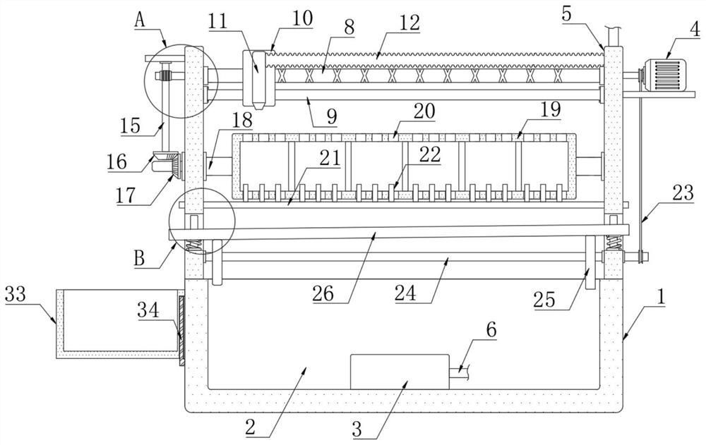
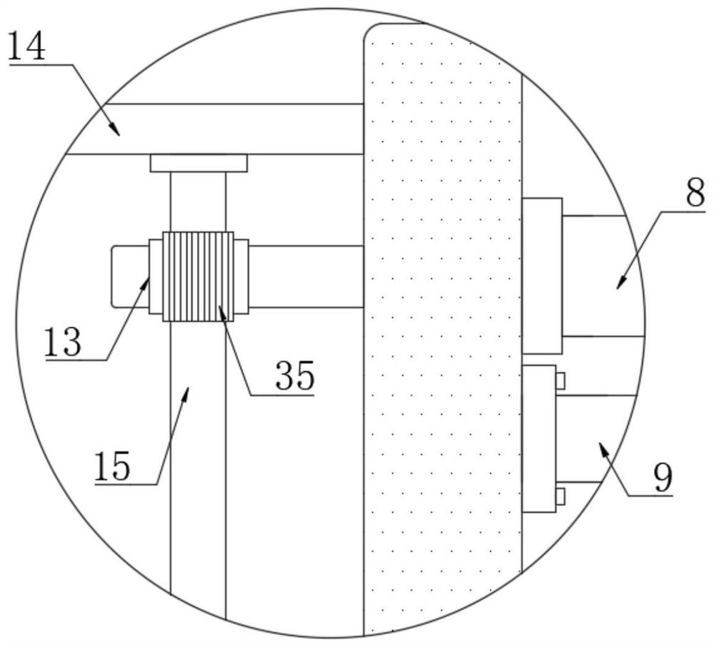
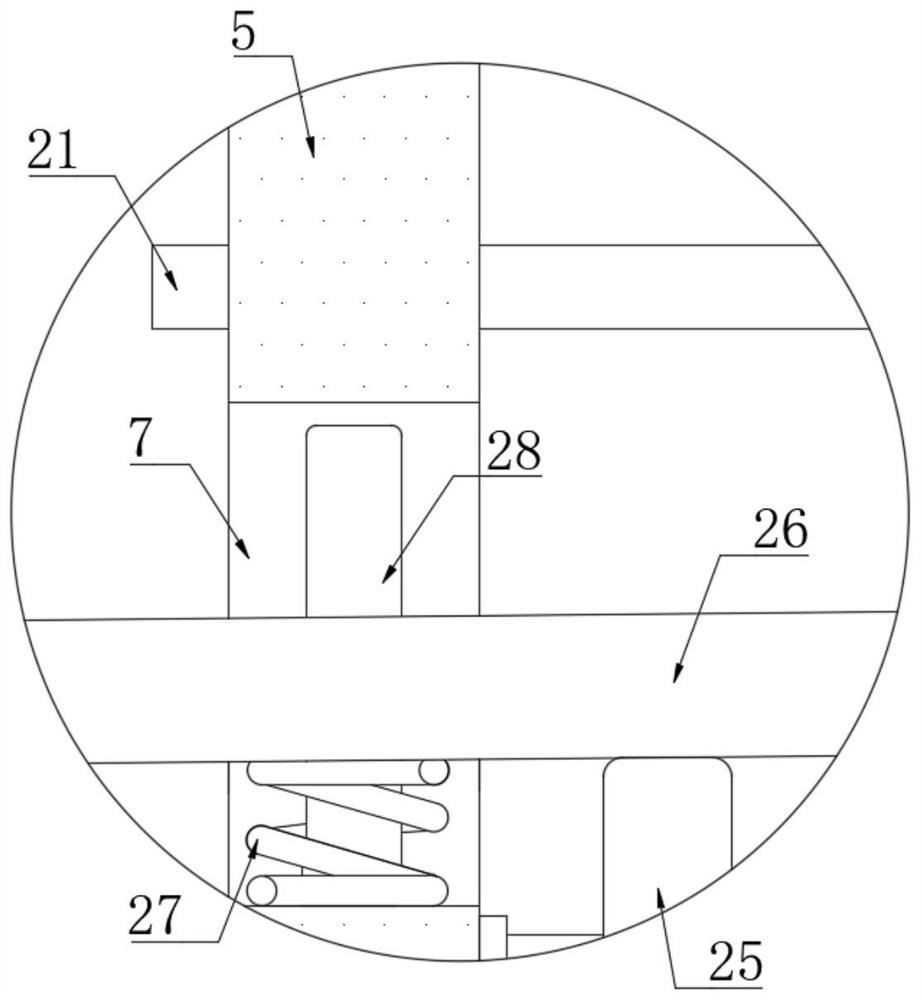
[0031] refer to Figure 1-6 , a kind of oiling equipment for hardware fittings, comprising a shell 1, the upper end of the shell 1 is provided with a placement tank 2, the oil required for processing is stored in the placement tank 2, and a liquid pump 3 is installed at the bottom of the placement tank 2, The liquid outlet of the liquid pump 3 is equipped with a connecting pipe 6, and the upper end of the housing 1 is symmetrically and fixedly connected with two mounting plates 5, and a reciprocating screw rod 8 is rotatably connected between the two mounting plates 5, and between the two mounting plates 5 The first guide rod 9 is fixedly connected, the reciprocating screw rod 8 is threadedly connected with the moving block 10, the first guide rod 9 runs through the moving block 10, the moving block 10 is equipped with a nozzle 11, and the nozzle of the nozzle 11 adopts an atomizing nozzle. The right side of 11 is equipped with a bellows 12, the right end of the bellows 12 is ...

Embodiment 2

[0042] refer to Figure 7-10 , the difference between this embodiment and Embodiment 1 is that: the two ends of the strip plate 21 pass through the corresponding mounting plate 5, the strip plate 21 is fixedly connected with a connecting block 29, and the connecting block 29 connects with the second spring 30 The side wall of the mounting plate 5 on the left side is elastically connected, a push rod 31 is installed on the first rotating rod 18 on the right side, and an inclined-plane block 32 is fixedly connected on the strip plate 21, and the push rod 31 cooperates with the inclined-plane block 32 , the push rod 31 can push the inclined block 32 to move to the right, and then drive the strip plate 21 to move to the right.

[0043] Compared with Embodiment 1, in this embodiment, when the first rotating rod 18 drives the rotating cylinder 19 to rotate, it further drives the push rod 31 to rotate. When the push rod 31 contacts the inclined block 32 and continues to rotate, it ca...


PUM


Abstract

The invention discloses oiling equipment for hardware fittings which comprises a shell, a placement groove is formed in the upper end of the shell, a liquid pump is mounted at the bottom in the placement groove, a connecting pipe is mounted at a liquid outlet of the liquid pump, two mounting plates are symmetrically and fixedly connected to the upper end of the shell, and a reciprocating lead screw is rotationally connected between the two mounting plates; a first guide rod is fixedly connected between the two mounting plates, a reciprocating screw rod is in threaded connection with a moving block, the first guide rod penetrates through the moving block, a spray head is mounted on the moving block, and a corrugated pipe is mounted on the right side of the spray head. According to the device, overturning oiling can be conducted on hardware, manual overturning of a machined part is not needed for oiling, impurities in oil can be filtered out through a filter screen plate, machined oil bodies are recycled, vibration of the filter screen plate can be achieved through a driving motor, the impurities can fall into a storage box, and workers can conveniently dump the impurities.

Description

technical field [0001] The invention relates to the technical field of hardware processing, in particular to a device for oiling hardware accessories. Background technique [0002] Hardware accessories refer to machine parts or components made of hardware, as well as some small hardware products, which can be used alone or as auxiliary tools, such as hardware tools, hardware parts, daily hardware, construction hardware and security supplies, etc., small hardware products Most of them are not final consumer goods, but are used as supporting products, semi-finished products and tools used in the production process for industrial manufacturing; [0003] In the process of processing hardware accessories, it is necessary to oil the hardware accessories to improve the service life of the hardware. However, for some plate-shaped or block-shaped accessories, it is necessary to oil all surfaces of the accessories during the oiling process. The operation is time-consuming and labor-i...

Claims


Application Information

Patent Timeline
Patent Type & Authority Applications(China)
IPC IPC(8): B05B13/04B05B13/02B05B15/40B05B16/20B08B1/00B08B13/00
CPCB05B13/041B05B13/0228B05B15/40B05B16/20B08B13/00B08B1/12
Inventor 吴修来
Owner 吴修来
Learn More