Spraying equipment for building materials

A technology for spraying equipment and building materials, which can be used in spraying devices, liquid spraying devices, etc., and can solve problems such as single function

Active Publication Date: 2021-05-25
新昌县品创建筑设计有限公司
View PDF6 Cites 0 Cited by
  • Summary
  • Abstract
  • Description
  • Claims
  • Application Information

AI Technical Summary

Problems solved by technology

[0002] Spraying equipment for building materials is a commonly used equipment in the construction field, but the general spraying equipment for building materials has a single function

Method used


Image

  • Spraying equipment for building materials
  • Spraying equipment for building materials
  • Spraying equipment for building materials

Examples


specific Embodiment approach 1

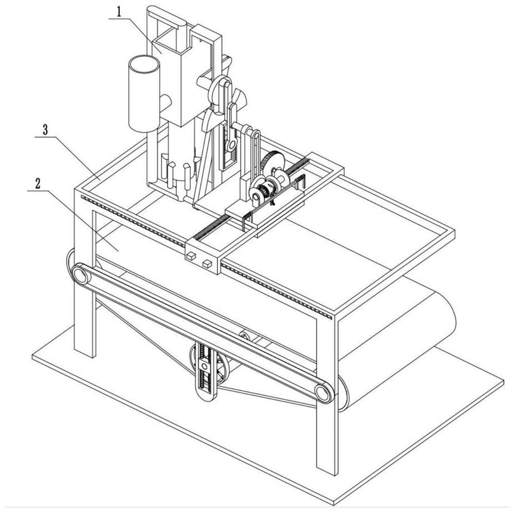
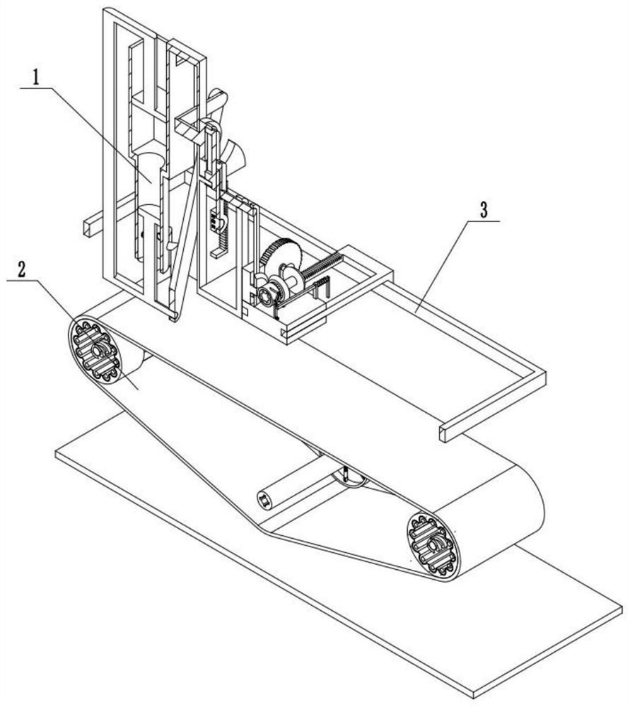
[0030] Combine below Figure 1-14 Description of this embodiment, a spraying equipment for building materials, including a spraying assembly 1, a carrying assembly 2, and a driving assembly 3, characterized in that: the spraying assembly 1 is connected to the driving assembly 3, and the carrying assembly 2 is connected with the drive assembly 3.

specific Embodiment approach 2

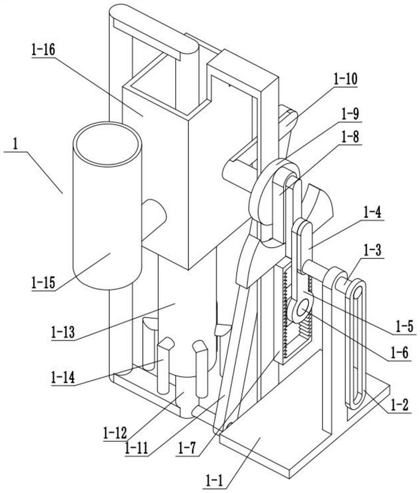
[0032] Combine below Figure 1-14 Describe this embodiment, this embodiment will further explain Embodiment 1, the spray assembly 1 includes a fixed bottom plate 1-1, a belt 1-2, a middle end rotating column 1-3, an eccentric rod 1-4, an eccentric Rod hinge rod 1-5, rectangular slider 1-6, swing rod 1-7, U-shaped rod 1-8, runner 1-9, eccentric rod 2 1-10, eccentric rod connecting rod 1-11, Piston rod 1-12, liquid spray sleeve 1-13, spray pipe 1-14, containing pipe 1-15, rectangular sleeve 1-16, upper piston 1-17, lower piston 1-18, inner end slot 1 1-19, the inner end clamping rod one 1-20, the inner end clamping rod push spring one 1-21, the middle end rotating column 1-3 is rotationally connected with the fixed bottom plate 1-1, the belt one 1-2 is connected with the middle end rotating column 1-3 are matingly connected, the eccentric rod 1-4 is fixedly connected with the middle end rotating column 1-3, the eccentric rod 1-4 is rotationally connected with the eccentric rod ...

specific Embodiment approach 3

[0034] Combine below Figure 1-14 Describe this embodiment, this embodiment will further explain the first embodiment, the bearing assembly 2 includes a bearing frame 2-1, a bearing bracket 2-2, a bearing belt 2-3, a connecting belt 2-4, a roller 2 -5, inner end screw rod 2-6, inner end sliding post 2-7, inner end sliding post push spring 2-8, roller two 2-9, inner end spiral groove rod 2-10, spiral groove 2-11, Matching sliding column 2-12, inner casing one 2-13, buffer sliding rod one 2-14, buffer sliding rod two 2-15, buffer spring one 2-16, buffer spring two 2-17, inner end casing Two 2-18, inner casing three 2-19, rectangular slider 2-20, rectangular slider slider 2-21, rectangular slider push spring 2-22, bearing bracket 2-2 and bearing outer frame 2- 1 is fixedly connected, the first roller 2-5 is rotationally connected with the bearing bracket 2-2, the bearing belt 2-3 is connected with the first roller 2-5, the bearing belt 2-3 is connected with the first roller 2-5,...


PUM


Abstract

The invention relates to the construction field, in particular to a spraying equipment for building materials. It can realize the spraying of building materials; the spraying effect can be adjusted according to the actual situation; the automatic reciprocating spraying of building materials can be realized to facilitate the improvement of spraying efficiency; the spraying position can be adjusted according to the actual situation. Including the injection assembly, the bearing assembly, and the driving assembly, so that the driving sleeve is connected with the transmission bevel gear 1, and then the direction of rotation of the bevel gear 2 is changed, and at the same time, the above-mentioned transmission relationship makes the bearing slide along the middle end. The slide bar slides in the opposite direction. When the bearing slide slides in the opposite direction along the middle end slide bar and contacts with the boundary of the middle end slide bar, through the above-mentioned transmission relationship, the drive sleeve drives the matching sleeve to cooperate with the drive bevel gear two. Once the connection is made, the drive sleeve is separated from the drive bevel gear, and the bearing slide plate slides in the opposite direction again along the middle end slide bar, thereby realizing the reciprocating spraying of building materials.

Description

technical field [0001] The invention relates to the construction field, in particular to a spraying equipment for building materials. Background technique [0002] Spraying equipment for building materials is a commonly used equipment in the construction field, but the general spraying equipment for building materials has a single function. Contents of the invention [0003] The purpose of the present invention is to provide a spraying equipment for building materials, which can realize spraying of building materials; can adjust the spraying effect according to actual conditions; can realize automatic reciprocating spraying of building materials, which is convenient to improve spraying efficiency; can be adjusted according to actual conditions Spray location. [0004] The purpose of the present invention is achieved through the following technical solutions: [0005] A spraying equipment for building materials, including a spraying assembly, a carrying assembly, and a dr...

Claims


Application Information

Patent Timeline
Patent Type & Authority Patents(China)
IPC IPC(8): B05B13/02B05B9/047
CPCB05B9/047B05B13/0221
Inventor 董青武
Owner 新昌县品创建筑设计有限公司
Why Eureka
Try Eureka