Soil turning device with tilling depth adjusting structure for agricultural implement and soil turning method thereof
A technology for adjusting structure and adjusting mechanism, applied in the field of agricultural machinery, can solve the problems of increasing manual labor, inconvenient digging, and reducing the function of deep-cultivation agricultural machinery, and achieves the effects of increasing practicability, increasing convenience, and reducing labor.
- Summary
- Abstract
- Description
- Claims
- Application Information
AI Technical Summary
Problems solved by technology
Method used
Image
Examples
Embodiment 1
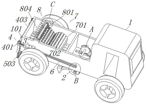
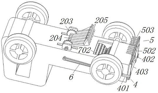
[0038] see figure 1 , Figure 4 and Figure 7 The tillage depth adjustment mechanism 2 includes an upper rotating shaft 201 bearing connected to the inner side of the agricultural machine body 1, and an equalized gear 202 is welded on the front and rear sides of the upper rotating shaft 201, and a first transmission gear 203 is meshed on the outer side of the lower part of the equalized gear 202. The inner side of the gear 203 is welded with a torsion spring rod 204, and the outer side of the torsion spring rod 204 is welded with a soil turning assembly 205 at an equidistant distance. mechanism, the agricultural machine body 1 is first driven to the field by the farming driver, and the servo motor on the back of the left side of the agricultural machine body 1 is started to drive the main shaft to drive the first sprocket mechanism 6 to rotate, so that the upper rotating shaft on the right side of the first sprocket mechanism 6 201 and the equally divided gears 202 on both s...
Embodiment 2
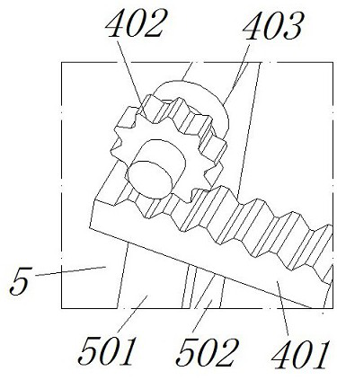
[0040] see figure 1 , image 3 and Figure 6 The difference from Embodiment 1 is that the grass collection mechanism 5 includes a connecting frame 501 welded on the bottom of the rack 401, a stop bar 502 is welded on the inner side of the connecting frame 501, and a drafting rod 503 is movable hinged on the inner side of the connecting frame 501, The front and rear left sides of the agricultural machinery body 1 are welded with connecting ears 101 as a support function. The turning mechanism 4 includes a rack 401 fixed on the left side of the cylinder 3 by a piston, and a second transmission gear 402 is engaged with the top of the rack 401. The second transmission The inner side of the gear 402 is welded with the first driven shaft 403, and the grass-taking mechanism 8 includes a second sprocket mechanism 801 that is keyed to the connecting roller 701 through the same main shaft, and the inner side of the second sprocket mechanism 801 is keyed with a second sprocket mechanism...
Embodiment 3
[0042] see figure 1 The difference from Embodiment 2 is that the mincing mechanism 7 includes a connecting roller 701 fixed on the outside of the main shaft, and the outside of the connecting roller 701 is welded with shredded pieces 702, and the shredded pieces 702 outside the two connecting rollers 701 are all staggered. , when the servo motor drives the main shaft to rotate, it can also drive the two large gears hidden between the front side of the agricultural machine body 1 and the front side of the connecting roller 701 to rotate inward at the same time, and at the same time, the two connecting rollers 701 will move toward the inner side at the same time. Rotating inside, when the two connecting rollers 701 rotate inward at the same time, it effectively drives the staggered twisting pieces 702 to grind the collected weeds, and then the ground weeds are discharged from the discharge port at the bottom of the agricultural machine body 1 Re-introduced into the farmland, so ...
PUM
 Abstract
Description
Claims
Application Information
 - R&D
- Intellectual Property
- Life Sciences
- Materials
- Tech Scout
- Unparalleled Data Quality
- Higher Quality Content
- 60% Fewer Hallucinations
Browse by: Latest US Patents, China's latest patents, Technical Efficacy Thesaurus, Application Domain, Technology Topic, Popular Technical Reports.
© 2025 PatSnap. All rights reserved.Legal|Privacy policy|Modern Slavery Act Transparency Statement|Sitemap|About US| Contact US: help@patsnap.com


