Dual-motor hybrid power transmission device
A hybrid power and transmission technology, applied in the field of dual-motor hybrid power transmission, can solve problems such as poor adaptability, large radial space, no pure engine operation mode, etc., and achieve compact structure, good power performance, and good economy Effect
- Summary
- Abstract
- Description
- Claims
- Application Information
AI Technical Summary
Problems solved by technology
Method used
Image
Examples
Embodiment 1
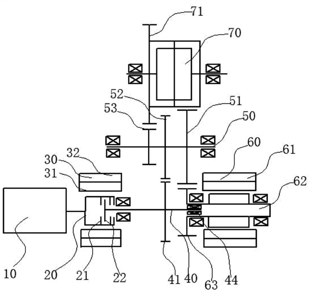
[0022] Such as figure 1 As shown, the dual-motor hybrid transmission includes an engine 10, a clutch 20, a first motor 30, a second motor assembly, and a transmission. The engine 10 is connected to the clutch 20, the clutch 20 cooperates with the first motor 30, and the transmission includes an input shaft assembly. , the countershaft assembly, the input shaft assembly includes the input shaft 40, the first input gear 41 arranged on the input shaft 40, the countershaft assembly includes the countershaft 50, the first counter gear 52 arranged on the countershaft 50, the differential The constant meshing gear 53, the input shaft 40 is connected with the clutch 20, the first input gear 41 meshes with the first intermediate gear 52, the differential constant meshing gear 53 is fixed with the intermediate shaft 50; the differential constant meshing gear 53 is connected with the differential The input gear 71 meshes, and the differential input gear 71 is fixed to the differential 70...
Embodiment 2
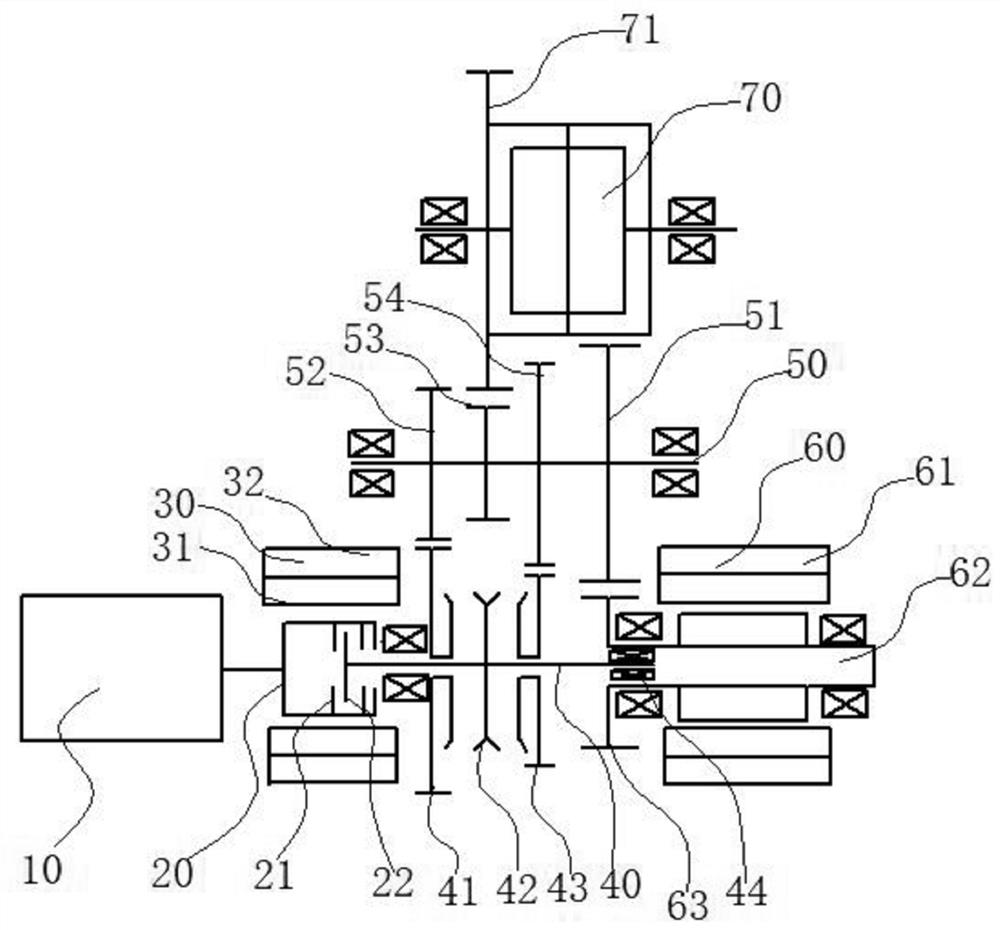
[0029] Such as figure 2 As shown, the difference between this embodiment and the embodiment is that the input shaft assembly further includes a second input gear 43, a first synchronizer 42 combined with the first input gear 41 or the second input gear 43 to transmit torque, the first The input gear 41 and the second input gear 43 are respectively rotatably arranged on the input shaft 40 relative to the input shaft 40 , and the first synchronizer 42 is fixed on the input shaft 40 . The intermediate shaft assembly further includes a second intermediate gear 54 meshing with the second input gear 43 , and the first motor output gear 51 , the first intermediate gear 52 and the second intermediate gear 54 are respectively fixed to the intermediate shaft 50 .
[0030] Through the above structure, the first input gear 41 and the second input gear 43 idling on the input shaft 40 mesh with the first intermediate gear 52 and the second intermediate gear 54 fixedly connected to the inte...
Embodiment 3
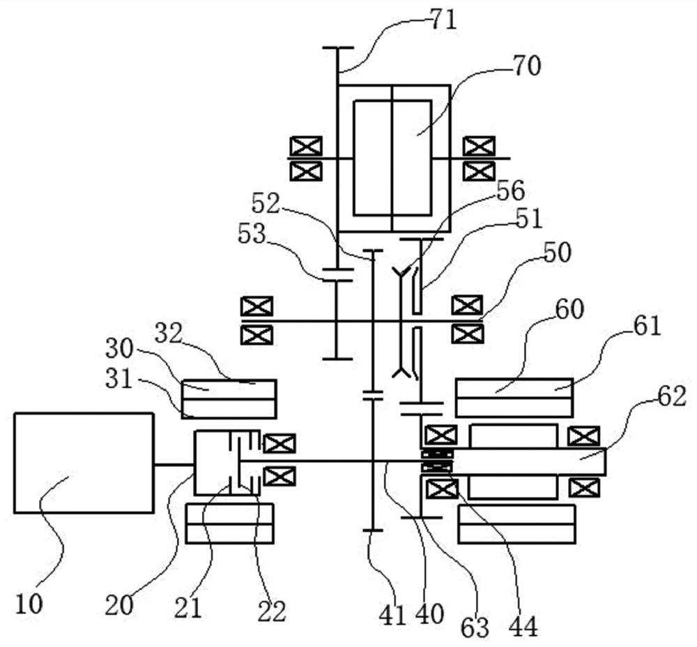
[0032] Such as image 3 As shown, the difference between the present embodiment and the first embodiment is that the first input gear 41 is fixed to the input shaft 40, the first intermediate gear 52 is fixed to the intermediate shaft 50, and the intermediate shaft assembly also includes an output gear combined with the first motor output gear 51. The second synchronizer 56 is used to transmit torque, and the second synchronizer 56 is fixed on the intermediate shaft 50 , and the first motor output gear 51 is rotatably arranged on the intermediate shaft 50 relative to the intermediate shaft 50 .
[0033]Through the above structure, the first input gear 41 fixedly connected to the input shaft 40 meshes with the first intermediate gear 52 fixedly connected to the intermediate shaft 50 to form an engine gear pair. The first motor input gear 63 meshes with the first motor output gear 51 idling on the intermediate shaft 50 to form a motor output gear pair. The second synchronizer 56...
PUM
 Abstract
Description
Claims
Application Information
 - R&D
- Intellectual Property
- Life Sciences
- Materials
- Tech Scout
- Unparalleled Data Quality
- Higher Quality Content
- 60% Fewer Hallucinations
Browse by: Latest US Patents, China's latest patents, Technical Efficacy Thesaurus, Application Domain, Technology Topic, Popular Technical Reports.
© 2025 PatSnap. All rights reserved.Legal|Privacy policy|Modern Slavery Act Transparency Statement|Sitemap|About US| Contact US: help@patsnap.com


